Oil box respiration device

A breathing device and oil tank technology, applied in the field of transformers, can solve problems such as seepage from the sealing surface on the top of the oil tank, high technical requirements for radiators, dirty transformers, etc., and achieve the effects of easy processing, reduced moisture content, and reduced pollution

Inactive Publication Date: 2008-09-17
CHINESE ELECTRICAL EQUIP GRP CO LTD
View PDF0 Cites 6 Cited by
  • Summary
  • Abstract
  • Description
  • Claims
  • Application Information

AI Technical Summary

Problems solved by technology

Now some transformers larger than 800kVA also adopt a fully sealed structure without an oil conservator. GB6451-1999 stipulates that a transformer with a capacity larger than 800kVA needs to be equipped with a gas protection device, but the gas protection device installed in a fully sealed transformer with a top inflatable structure is not can play a very good protective role
The transformer with a special radiator breathes by the expansion of the radiator. This breathing method has high technical requirements for the radiator, which leads to high cost of this type of radiator, and sometimes when the expansion of the oil exceeds the heat dissipation The amount of expansion of the transformer, the oil will seep from the sealing surface on the top of the oil tank, the transformer looks particularly dirty when there is dust attached, which is why we see many of these transformers dirty
If you want to fully satisfy the expansion of oil, you need to increase the number of radiators, and choose an expansion radiator with a good elastic modulus, which will greatly increase the cost

Method used


Image

  • Oil box respiration device
  • Oil box respiration device
  • Oil box respiration device

Examples


Embodiment Construction

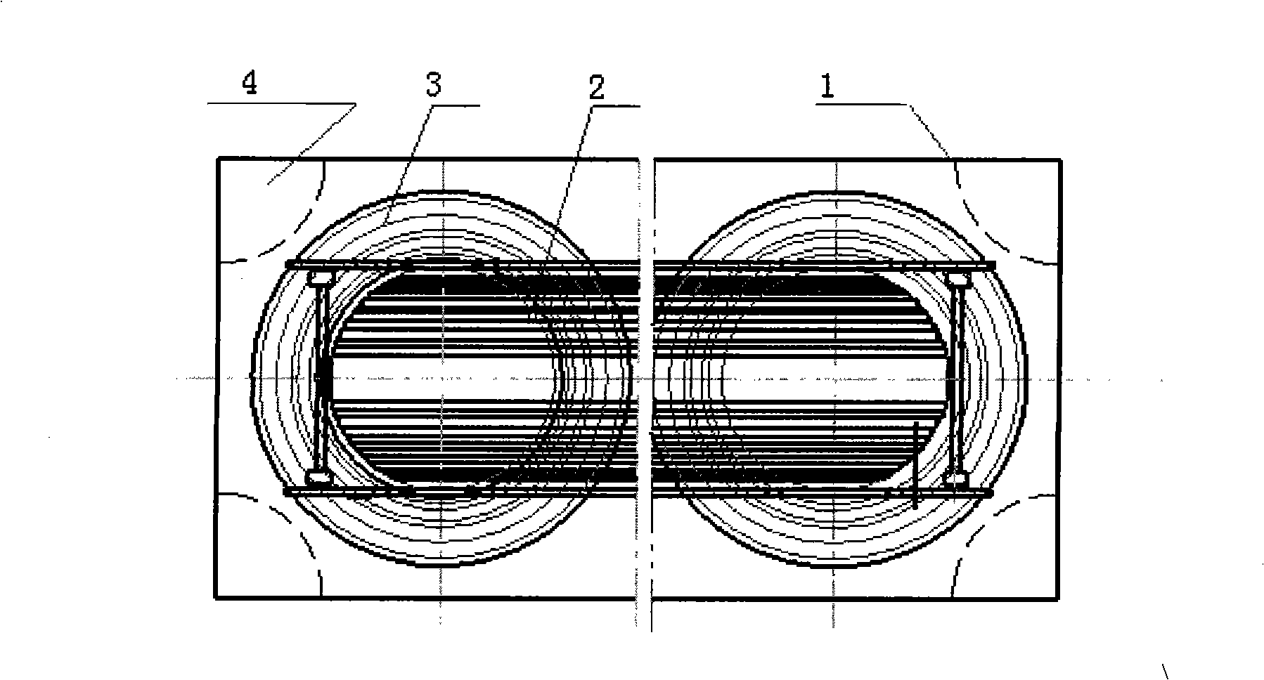
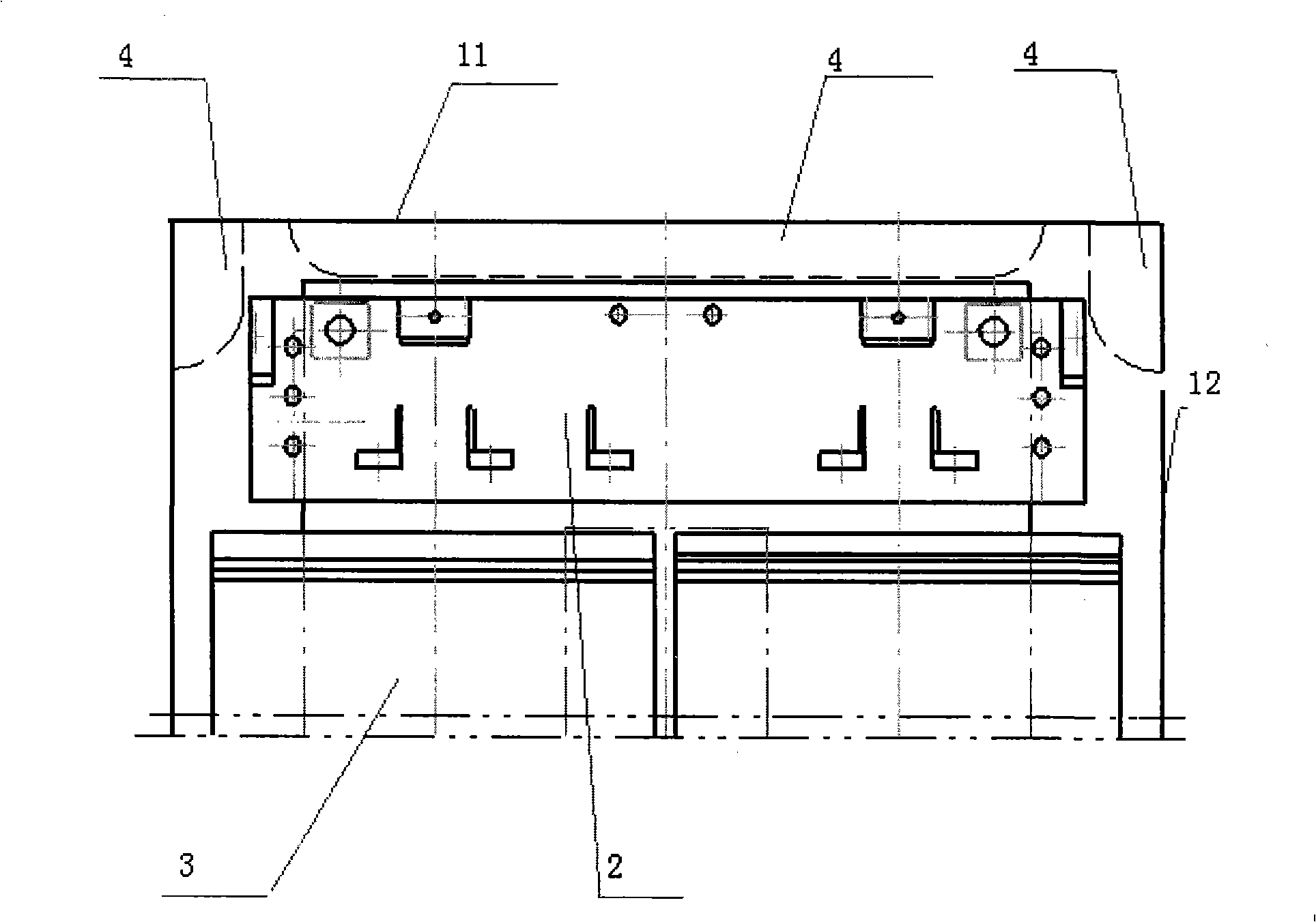
[0025] The present invention is described in detail below in conjunction with accompanying drawing: As shown in the figure, the present invention comprises the cuboid fuel tank 1 that is made of tank cover 11, tank wall 12, tank bottom 13, and the center of cuboid fuel tank 1 is provided with iron core 2, and the periphery of iron core 2 The coil 3 is wound, and at least one capsule 4 is arranged in the cuboid oil tank 1 .

[0026] The above-mentioned capsule 4 is arranged at the junction of the case cover 11 and the case wall 12 . The above-mentioned capsule 4 is arranged at the junction of the box bottom 13 and the box wall 12 .

[0027] The above-mentioned capsule 4 is strip-shaped or ring-shaped.

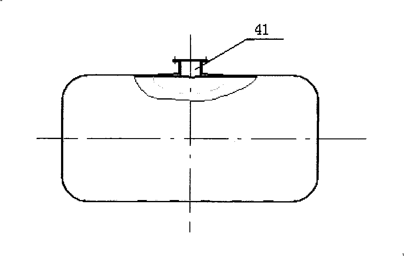
[0028] Above-mentioned capsule 4 is a sealed capsule. Fill the sealed capsule with dry air or nitrogen.

[0029] The above-mentioned capsule 4 is an open capsule. The open end 41 of the open capsule is connected to the moisture absorber 6 through the connecting pipe 5, and a...


PUM


Abstract

An oil tank breathing device relates to the technical field of a transformer, more particularly relates to the filed of a sealed container such as an oil immersed transformer, an instrument transformer, a reactor and an oilcan that need to adjust the capacity owing to hot-swelling and cold-shrinking. The invention comprises a rectangular oil tank composed by a tank cover, tank walls and a tank bottom, center of the rectangular oil tank is provided with an iron core whose outer circumference is wound with coils, at least one capsule is provided inside the rectangular oil tank. The invention, through a sealed capsule or an opening capsule, solves the breathing issues of the transformer, the instrument transformer, the reactor and the oilcan and removes an oil-storage cabinet, so the full seal is practically realized and gas protecting devices of above transformers can actually protect. The oilcan does not absorb the water and the air in the entire process of transportation, guaranteeing the performance of transporting the liquid and saving the cost; and the liquid will not leak out form the sealed face on the top of the oil tank, which is simple in structure, convenient for processing and cleaning the surface of the transformer, and reduces pollution to the environment.

Description

technical field [0001] The invention relates to the technical field of transformers, in particular to the field of oil-immersed transformers, transformers, reactors, oil tanks and other sealed containers that require capacity adjustment due to thermal expansion and contraction. Background technique [0002] Currently used oil conservator for transformers, transformers, reactors, etc. generally adopts open oil conservator or fully sealed oil conservator. [0003] The open oil conservator is used, and the oil is in direct contact with the atmosphere. The fully sealed oil conservator is based on the open oil conservator and some devices are added to prevent the air from directly contacting the transformer oil. Currently, three forms are used: metal bellows, Diaphragm, capsule. [0004] When the ambient temperature changes or the transformer is running, the temperature of the oil increases or decreases, which will cause the expansion and contraction of the transformer oil. The ...

Claims


Application Information

Patent Timeline
IPC IPC(8): H01F27/14
Inventor 白忠东范华朱桂英周书亮张永华蔡智勇
Owner CHINESE ELECTRICAL EQUIP GRP CO LTD
Why Eureka
Try Eureka