Supercharge Your Innovation With Domain-Expert AI Agents!

Cyclonic separation apparatus

A technology of cyclone separation and cyclone separator, which is applied in the direction of cyclone device, device whose axial direction can be reversed, suction filter, etc., and can solve problems such as cyclone clogging and dust gas cannot be loaded smoothly

Inactive Publication Date: 2008-10-01
HOOVER LIMITED
View PDF3 Cites 0 Cited by
  • Summary
  • Abstract
  • Description
  • Claims
  • Application Information

AI Technical Summary

Problems solved by technology

However, in this case, the high-efficiency cyclones are not equidistantly distributed on the periphery of the separator unit, so that the dust-laden gas cannot be smoothly loaded into these cyclones, thus causing some cyclones to clog

Method used


Image

  • Cyclonic separation apparatus
  • Cyclonic separation apparatus
  • Cyclonic separation apparatus

Examples


Embodiment Construction

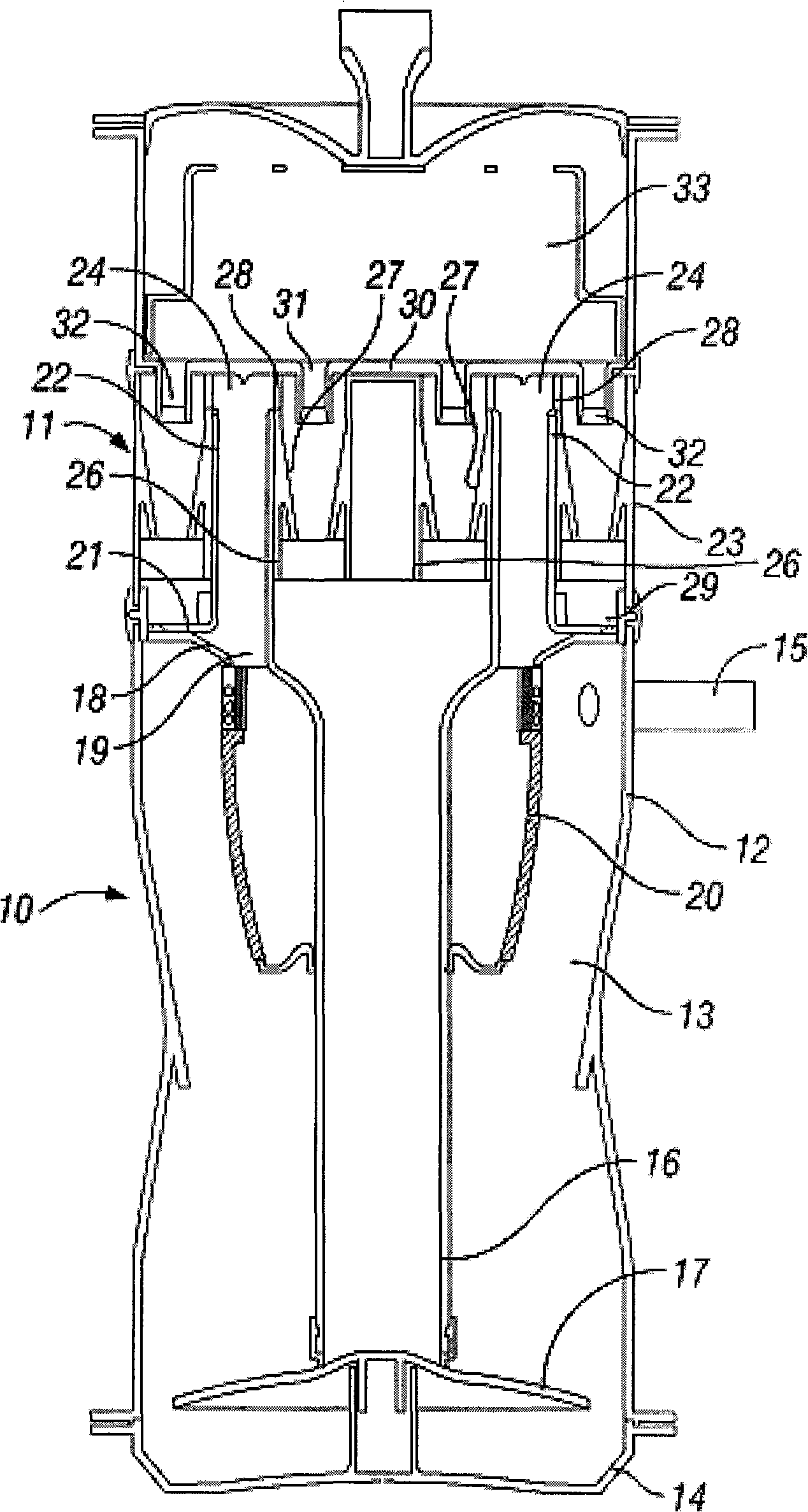
[0032] Refer to the attached figure 1 , showing a detached section of an upright vacuum cleaner. The detachment is mounted to a chassis (not shown) containing a handle, the lower end of which is pivotally connected to a wheel-shaped floor cleaning head containing a rotatable agitating brush.

[0033] The separation part comprises a substantially cylindrical upright housing housing at its lower and upper ends respectively a first separation step 10 and a second separation step 11 fluidly connected to the first step 10. downstream.

[0034] The first step 10 comprises a tubular side wall 12 defining a cyclone chamber 13 of circular section. The lower end of the tubular side wall 12 is provided with a closure 14 which can be opened to allow the chamber 13 to be emptied of separated dirt and dust.

[0035] An inlet duct 15 for conveying dirt and dust laden air from the floor cleaning head extends tangentially into the upper end of the tubular side wall 12 of the first step 10 ....


PUM


Abstract

A cyclonic separation apparatus comprising at least two series connected separation stages and a receptacle for collecting material separated by the separation stages, is described. The first stage comprises a first cyclone separator and the second stage comprises a plurality of parallel connected second cyclone separators. The first and second separation stages are connected by at least one transfer duct which extends through the receptacle and transfers fluid that has been partly cleaned by the first separation stage, to the second separation stage.

Description

technical field [0001] The present invention relates to cyclonic separation devices. Background technique [0002] Cyclone separation devices are well known devices for removing particulates from a gas stream without the use of filters. Cyclone separators have found application in vacuum cleaners to separate dirt and dust from an air stream. It is well known that the separation efficiency of a cyclone depends on the force applied to the particles in the air stream, which is determined by: [0003] f=2mv 2 / d here [0004] f = force applied to the particle [0005] m = mass of particle [0006] v = velocity of flow [0007] d = diameter of cyclonic air flow [0008] It can thus be noted that the separation efficiency is inversely proportional to the diameter of the cyclone chamber, which makes smaller diameter cyclones more suitable for separating lighter particles than larger cyclones. It is thus known to vacuum cleaners comprising a first upstream se...

Claims


Application Information

Patent Timeline
Patent Type & Authority Applications(China)
IPC IPC(8): B04C5/24
CPCB04C5/14B04C5/12A47L9/165A47L9/1641A47L9/1658B04C5/28A47L9/16A47L9/1608A47L9/1616B04C5/24
Inventor 戴维·本杰明·史密斯
Owner HOOVER LIMITED
Features
  • R&D
  • Intellectual Property
  • Life Sciences
  • Materials
  • Tech Scout
  • Unparalleled Data Quality
  • Higher Quality Content
  • 60% Fewer Hallucinations
Learn More