Spinning device

A spinning device and spinning technology, which are applied in spinneret assemblies, textiles and papermaking, etc., can solve the problems of large operation, cost, connection that cannot form a pressure seal, etc., and achieve the effect of small force consumption

Inactive Publication Date: 2008-10-01
OERLIKON TEXTILE GMBH & CO KG
View PDF1 Cites 5 Cited by
  • Summary
  • Abstract
  • Description
  • Claims
  • Application Information

AI Technical Summary

Problems solved by technology

[0005] In principle, however, this threaded connection has the disadvantage that the spinneret assembly must be mounted with considerable operational effort during multiple revolutions
Although this disadvantage can be avoided by means of a snap-in connection, here the connecting elements required to form the snap-in connection require relatively high manufacturing costs
[0006] It is also known from EP0163248 that the snap-in connection is designed as a multi-thread thread, but has the disadvantage that, when inserting and rotating the spinning nozzle assembly, the thread engages one thread earlier, so that a pressure-tight connection cannot be formed

Method used


Image

  • Spinning device
  • Spinning device
  • Spinning device

Examples


Embodiment Construction

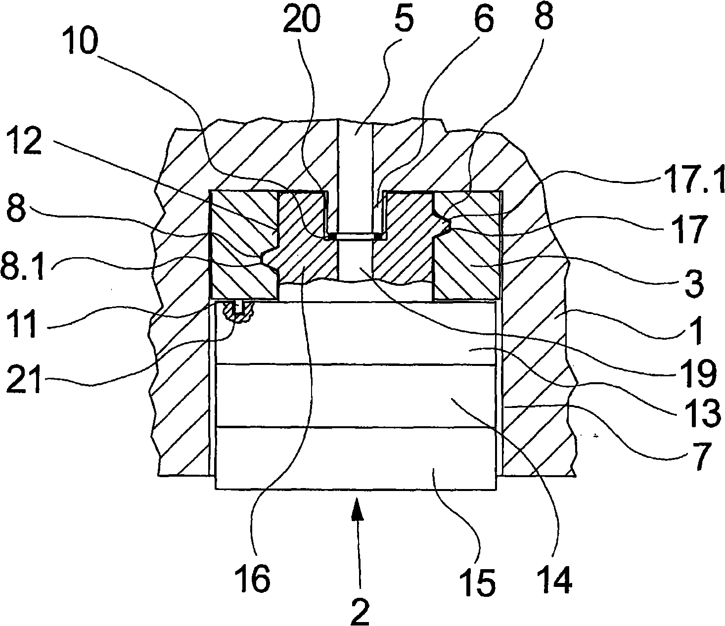
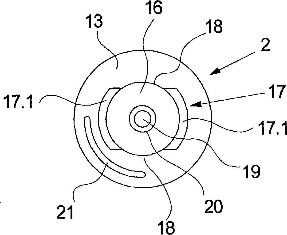
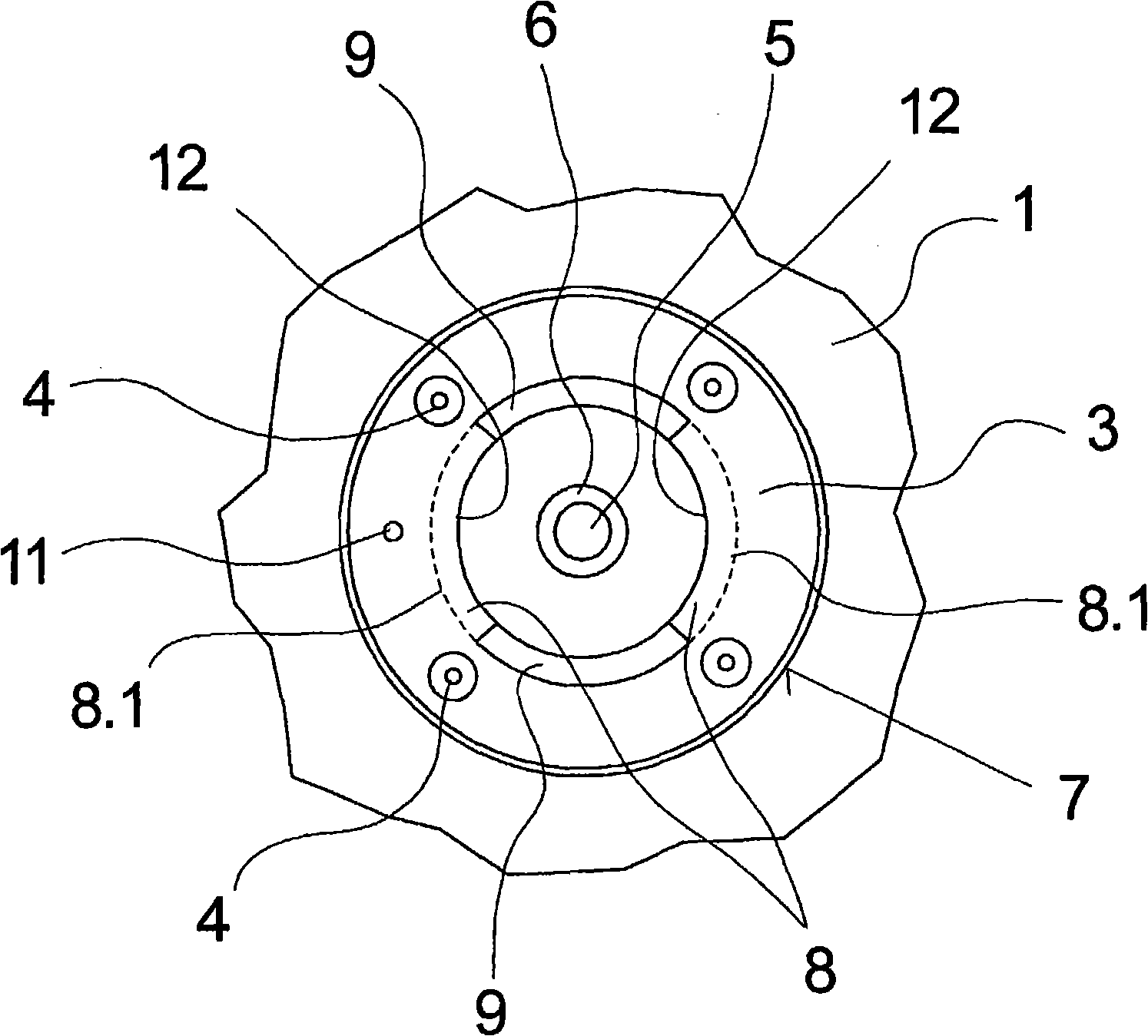
[0027] Figures 1 to 3 A first embodiment of the spinning device according to the invention is shown in several illustrations. figure 1 shows a schematic transverse cross-sectional view, figure 2 shows a top view of the spinning nozzle assembly, while image 3 Shows a top view of the underside of the nozzle holder. If it is not clear which figure is referred to, the following description applies to both figures.

[0028] The exemplary embodiment comprises a nozzle holder 1 which has a melt connection. The nozzle holder 1 is only partially shown in this exemplary embodiment. Typically such nozzle holders are elongated in order to accommodate a plurality of spinning nozzle assemblies on the underside.

[0029] The nozzle holder 1 is connected via a melt connection 5 via a melt line, not shown here, to a melt source. A nozzle receiving opening 7 is formed on the underside of the nozzle holder 1 for receiving the spinning nozzle assembly 2 . The nozzle receiving opening 7 ...


PUM

PropertyMeasurementUnit
diameteraaaaaaaaaa

Abstract

The invention relates to a spinning device for melting and spinning a plurality of single filament, having a nozzle holder and a detachable spinning nozzle assembly held on a melt joint of the nozzle holder with a melt inlet. The nozzle holder has a holding part for accepting the spinning nozzle assembly with thread screw at the lower side for fixing function. The spinning nozzle assembly has a corresponding holding part with corresponding thread screw for cooperation with the holding part. For fixing and high sealing between the spinning nozzle assembly and the nozzle holder with partly rotation, according to the invention, the corresponding thread screw forms from external thread screw of a thread section with one full circle only on the corresponding holding part. The thread section is a plurality of thread gaps on circumference direction. The thread screw forms from inner thread of a thread groove with one full circle only on the holding part. The thread groove stops by a plurality of thread cuts in circumference. The thread gap of the external thread has an arc size more than that of the thread cut of the inner thread each. The quantity of the thread gap is identical with that of the thread cut.

Description

technical field [0001] The invention relates to a spinning device for melt spinning a plurality of monofilaments according to the preamble of claim 1 . Background technique [0002] In the manufacture of synthetic yarns, it is required to extrude a polymer melt into a plurality of extremely fine filaments. For this purpose, the polymer melt is extruded through a plurality of fine capillaries. The capillaries are arranged in the spinneret, which is combined with the melt distribution plate and the filter element to form a structural unit. Such a structural unit is also referred to as a spinneret assembly. Such spinneret assemblies require periodic cleaning due to melt deposits that deposit in the plates and holes of the spinneret assembly over time. For this purpose, such spinneret assemblies are known which are detachably fastened to a nozzle holder, wherein the nozzle holder has a melt connection which cooperates with a melt inlet in the spinneret assembly. Here, the fa...

Claims


Application Information

Patent Timeline
Patent Type & Authority Applications(China)
IPC IPC(8): D01D4/00D01D4/08
CPCD01D4/02
Inventor G·许特
Owner OERLIKON TEXTILE GMBH & CO KG
Why Eureka
Try Eureka