Sheet metal assembly line

An assembly line and assembly line technology, which is applied in the direction of transportation and packaging, conveyor control devices, conveyor objects, etc., can solve the problem of high cost, achieve the effect of reducing production cost, reducing production cost, and good economic benefits

Pending Publication Date: 2021-04-20
SUZHOU YUESHENG PRECISION MACHINERY MFGCO
View PDF0 Cites 0 Cited by
  • Summary
  • Abstract
  • Description
  • Claims
  • Application Information

AI Technical Summary

Problems solved by technology

[0002] During the production and assembly of sheet metal parts, they can be assembled on the circulating assembly line. The existing circulating assembly line generally uses a motor-driven lifting device to transfer the tooling plate up and down. The cost of some transmission mechanisms such as motors is relatively high, and other Precisely controlling the amount of motor rotation to ensure that the movement is in place requires stepping motors, servo motors, etc., which increases the cost of production
[0003] In addition, if another transmission method is used, the new transmission method may bring new problems, such as how to control the specific transmission logic, when to control the lifting, how to ensure that there are no other accidents during the transmission process, and the transmission of the tooling board. Protection is a problem that needs to be solved

Method used


Image

  • Sheet metal assembly line
  • Sheet metal assembly line
  • Sheet metal assembly line

Examples


Embodiment Construction

[0026] The technical solutions of the present invention will be further described below in conjunction with the accompanying drawings and through specific embodiments.

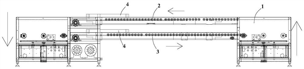
[0027] An embodiment of the present invention provides a sheet metal assembly line. Sheet metal parts are placed on the tooling board on the assembly line, and multiple stations are set on the assembly line. The circulating tooling board facilitates production, and workers do not need to move their positions. Continue to operate production.

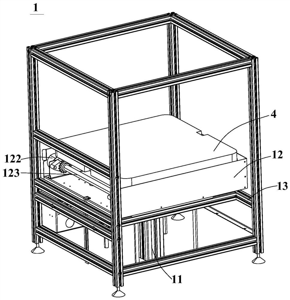
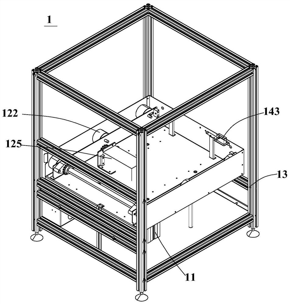
[0028] Specifically, such as figure 1 As shown, a kind of circulation assembly line of the present embodiment comprises upper assembly line 2, lower assembly line 3 and lifting device 1, and lifting device 1 comprises frame 13, is arranged on the jacking cylinder 11 on frame 13, is arranged on jacking cylinder The transmission mechanism 12 and the induction mechanism at the output end of 11, the jacking cylinder 11 includes a rising state and a falling state, in the risi...


PUM


Abstract

The invention discloses a metal plate assembly line. The metal plate assembly line comprises an upper assembly line, a lower assembly line and lifting devices, wherein each lifting device comprises a jacking cylinder, a conveying mechanism arranged at an output end of the jacking cylinder and an induction mechanism; the upper assembly line is provided with a candidate area trigger part; and each induction mechanism comprises a protection trigger part and a lifting trigger part which are sequentially arranged in the direction that tool plates enter the corresponding lifting device, and the distance between each protection trigger part and the corresponding lifting trigger part is smaller than the lengths of the tool plates in the conveying direction. By controlling the candidate area trigger part, the protection trigger parts and the lifting trigger parts, the jacking cylinders can ascend or descend only when certain conditions are met, no accident is generated through cooperation of the candidate area trigger part, the protection trigger parts and the lifting trigger parts, the next step of movement is protected every time the tool plates trigger one trigger part, and new problems are avoided, therefore, a new movement form can be perfectly met through use of the jacking cylinders, the production cost is reduced, and the economic benefit is good.

Description

technical field [0001] The invention relates to the production field of sheet metal parts, in particular to a sheet metal assembly line. Background technique [0002] During the production and assembly of sheet metal parts, they can be assembled on the circulating assembly line. The existing circulating assembly line generally uses a motor-driven lifting device to transfer the tooling plate up and down. The cost of some transmission mechanisms such as motors is relatively high, and other Precisely controlling the amount of motor rotation to ensure that the movement is in place requires stepping motors, servo motors, etc., which increases the cost of production. [0003] In addition, if another transmission method is used, the new transmission method may bring new problems, such as how to control the specific transmission logic, when to control the lifting, how to ensure that there are no other accidents during the transmission process, and the transmission of the tooling boa...

Claims


Application Information

Patent Timeline
Patent Type & Authority Applications(China)
IPC IPC(8): B65G23/24B65G15/00B65G43/08B65G47/74
Inventor 杨浩何章兵
Owner SUZHOU YUESHENG PRECISION MACHINERY MFGCO
Why Eureka
Try Eureka