Roof ventilation device and method thereof

A ventilation device and ventilation volume technology, applied in ventilation system, space heating and ventilation, heating methods, etc., can solve problems such as large ventilation volume, unbalanced ventilation volume, and a single roof ventilation device cannot meet the ventilation volume, etc., to achieve balance The effect of adjusting the wind force and balancing the ventilation volume

Inactive Publication Date: 2008-10-01
SHANGHAI NAN YANG MODEL HIGH SCHOOL
View PDF0 Cites 0 Cited by
  • Summary
  • Abstract
  • Description
  • Claims
  • Application Information

AI Technical Summary

Problems solved by technology

However, in the existing products and technologies, the problems encountered are as follows: one is that the exhaust air cannot be effectively started when the natural wind is weak; the other is that under normal wind conditions, a single roof ventilation device cannot meet the large ventilation volume The third is that when the natural wind is strong, the ventilation volume is also very large, and the ventilation volume cannot be balanced.

Method used


Image

  • Roof ventilation device and method thereof
  • Roof ventilation device and method thereof
  • Roof ventilation device and method thereof

Examples


Embodiment 1

[0040] combine figure 1 , figure 2 , for the following description.

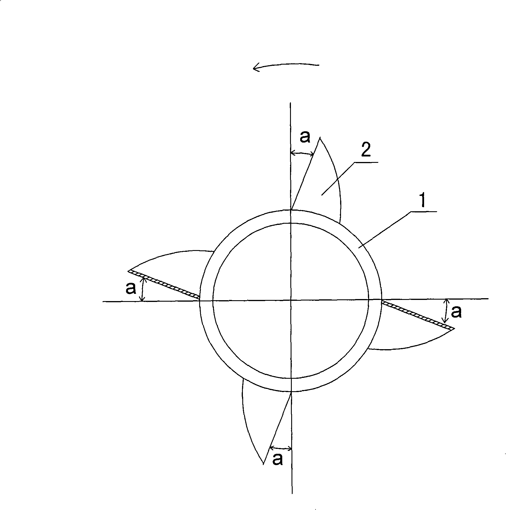
[0041] In the first embodiment, the rotating body is a hollow cylinder 1 . figure 1 The big arrow at the top in the middle represents: under the blowing of the wind, the direction in which the wind blade 2 and the rotating body rotate. In all documents of the present invention, "front" represents the same direction as the large arrow, and "rear" represents the opposite direction to the large arrow.

[0042] figure 1 Among them, there are 2 four blades in total. But in the present invention, the number of fan blades 2 is all possible from 2 to 20 pieces.

[0043] figure 1 The a marked in means that the fan blade 2 is not installed vertically on the hollow cylinder 1, but the fan blade 2 has a backward angle a, which should be considered and determined in combination with other shapes.

[0044] figure 1 Among them, the fan blade 2 section on the left is the situation that the fan blade 2 is cut in the...

Embodiment 2

[0054] The following combination image 3 , Figure 4 ,Be explained.

Embodiment 2

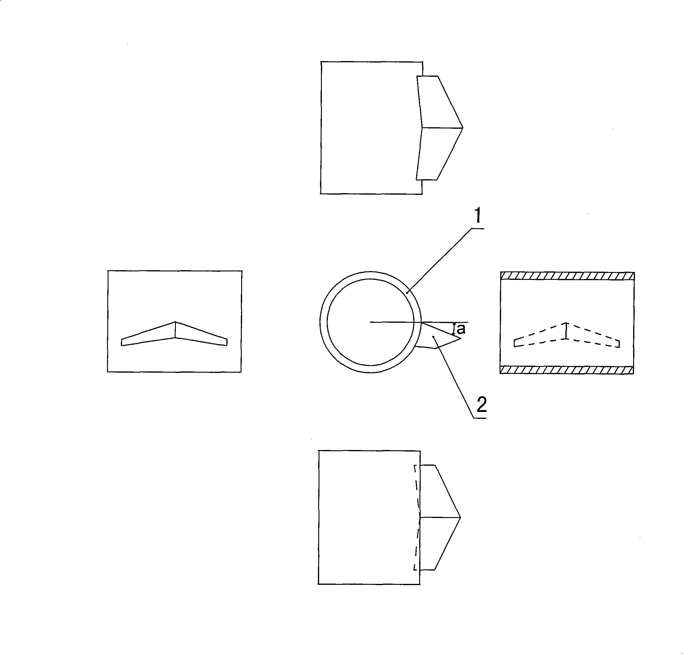
[0055] The difference between embodiment 2 and embodiment 1 is mainly that in embodiment 2, the blades 2 in the shape of a broken line are used.

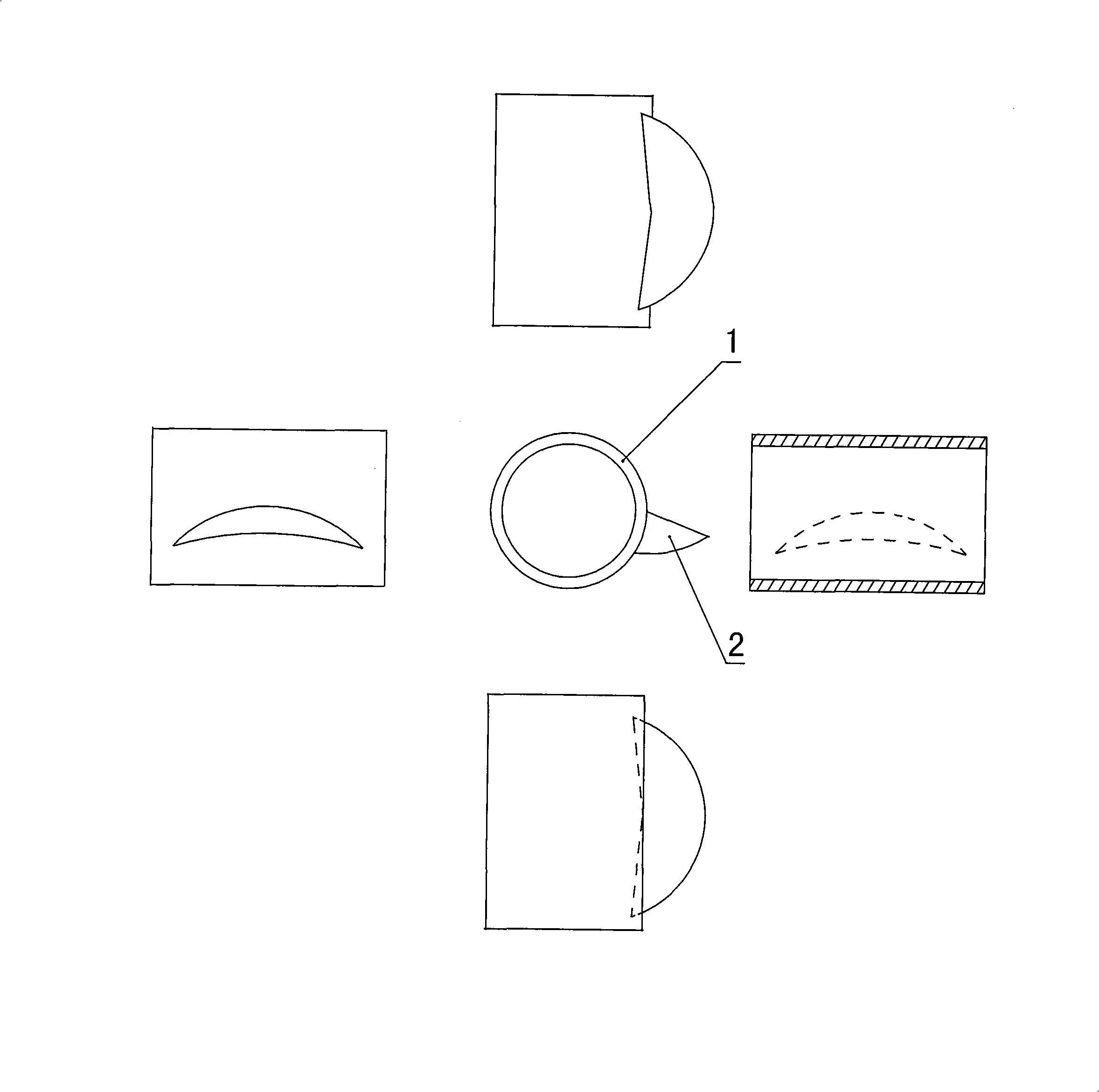
[0056] image 3 It is a schematic diagram of the present embodiment and the zigzag fan blade 2 . image 3 The center is the main view; the right is the left view; the left is the right view; the bottom is the top view, the dotted line is the intersecting line between the fan blade 2 and the hollow cylinder 1 that can be seen imaginary; the top is the bottom view, and the inner two broken lines are The intersecting line where the fan blade 2 and the hollow cylinder 1 intersect.

[0057] Figure 4 yes image 3 A three-dimensional schematic diagram of the zigzag fan blade 2 .

[0058] exist image 3 , Figure 4 Among them, the central part of the fan blade 2 protrudes forward in a broken line shape; the middle part of the outer edge of the fan blade 2 protrudes outwards in a broken line shape; the fan blades 2 are arranged at equ...


PUM


Abstract

The present invention discloses a roof ventilation device and method. The technical project is: a base, a revolving body, a fan blade (2); also a regulating mechanism of ventilation quantity, the rotary slice situated in a rotating body to rotating joint with the revolving body; the bottom of the rotating joint has a projecting thing for fixing in the rotating body, the top of the rotating flaking has a finite bit-slice for fixing in the rotating body. The center part of the fan blade (2) is projecting onwards with the shape of circular arc, or polygonal-shape, circular arc segment adding straight line segment; the external side peripheral middle part of the fan blade (2) projecting outward with the shape of circular arc, or fold line shape, or circular arc segment adding straight line segment. The dispose position spacing of the fan blade (2) is equal, the direction of tile being identical, and the angle of slope (a) being identical. The present invention possesses the beneficial effects: the air exhausting can be start effectively when having weak natural wind; larger ventilation quantity can be provided when being normal wind force; the pneumatic effect of proportional control can be reached with appropriate ventilation quantity when having great wind force.

Description

technical field [0001] The invention relates to the field of building ventilation, in particular to a roof ventilation device. Background technique [0002] Roof ventilation device (roof hood), is a traditional product. However, in the existing products and technologies, the problems encountered are as follows: one is that the exhaust air cannot be effectively started when the natural wind is weak; the other is that under normal wind conditions, a single roof ventilation device cannot meet the large ventilation volume The third is that when the natural wind is very strong, the ventilation volume is also very large, and the ventilation volume cannot be balanced. Contents of the invention [0003] The present invention can overcome the deficiencies of the prior art, and provides a roof ventilation device and its method, which can effectively start the exhaust when the natural wind is weak, and meet the requirement of relatively large ventilation volume under normal wind con...

Claims


Application Information

Patent Timeline
Patent Type & Authority Applications(China)
IPC IPC(8): F24F7/02
Inventor 邵波然吴国华周骏陆逸丰奚若成
Owner SHANGHAI NAN YANG MODEL HIGH SCHOOL
Why Eureka
Try Eureka