Air tightness rotating backblowing device for cloth bag dust remover

A bag filter, reverse blowing technology, applied in chemical instruments and methods, dispersed particle separation, dispersed particle filtration, etc., can solve the problems of high air leakage rate, poor cleaning performance, unbalanced injection pressure, etc., to increase the use of Long life, low maintenance cost, good cleaning effect

Inactive Publication Date: 2011-07-27
QINHUANGDAO QINGQING ENVIRONMENTAL PROTECTION EQUIP
View PDF0 Cites 0 Cited by
  • Summary
  • Abstract
  • Description
  • Claims
  • Application Information

AI Technical Summary

Problems solved by technology

At present, in the commonly used rotary reverse blowing bag filter, whether it is domestic or foreign, the common problem is the high air leakage rate, which makes the injection pressure unstable and the dust cleaning performance is poor. The main reason is the connection between the butt injection port and the dust collector The sealing performance between the chamber walls is poor. This is to meet the needs of the rotary positioning of the anti-blowing device, so that there is still a certain gap between the blowing port and the box wall, such as image 3 , Figure 4 As shown, it obviously leads to air leakage, which reduces the blowing pressure and blowing effect of the reverse blowing; at the same time, because the leaked gas is mixed into the air flow, the pressure of the system is unbalanced, and the blowing pressure is also unbalanced.

Method used


Image

  • Air tightness rotating backblowing device for cloth bag dust remover
  • Air tightness rotating backblowing device for cloth bag dust remover
  • Air tightness rotating backblowing device for cloth bag dust remover

Examples


Embodiment Construction

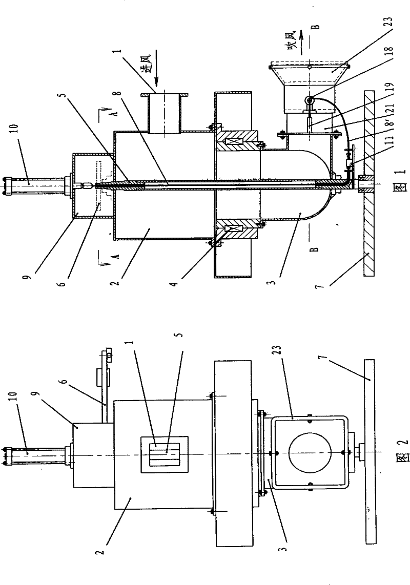
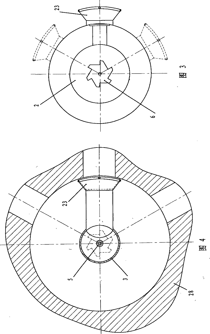
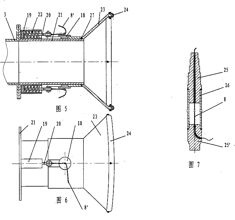
[0021] Depend on Figure 1 ~ Figure 2 It can be seen that the airtight rotary anti-blowing device for the bag filter of the present invention includes the anti-blowing box 2 that is rotatably connected to the upper part of the rotating shaft 5 and the right-angled blowing pipe joint 3 that is fixedly connected to the lower part. The lower end of the rotating shaft 5 protrudes and is fixed on the dust collector. The bracket 7 on the box body 28 is rotatably connected, and the upper part of the blowing pipe joint 3 is fixedly connected with the lower part of the anti-blowing box body 2 through the rotating part 4, wherein the rotating shaft 5 is a hollow structure, and the first drag cable 8 is housed in the rotating shaft 5. The upper end of a drag cable 8 passes through the rotating shaft 5 and is fixedly connected with the piston rod of the cylinder 10 installed on the top of the support frame 9 through the rigging turnbuckle 16', see Figure 8 . The support frame 9 is fixed...


PUM


Abstract

The invention provides an air-impermeable reverse blowing device used in a bag-type dust collector, comprising a revolving shaft, a reverse blowing case body, a jetting pipe joint and a bracket, wherein, the structure of the revolving shaft is hollow and a stay cable is arranged in the revolving shaft; the upper end of the stay cable is fixedly connected with a piston rod of a cylinder which is arranged on the upper part of the reverse blowing case body and the lower end of the stay cable crosses horizontally from the lower part of the revolving shaft and is connected with a sliding rod on a base plate; the other end of the sliding rod is connected with an intermediate plate; two sides of the intermediate plate respectively get around a guidepost by the stay cable and are symmetrically and fixedly connected with stretching ends of spring shafts arranged in two spring sleeves; the two spring sleeves are respectively arranged and fixed symmetrically on the outer wall of a cylinder whichis horizontally connected with the lower part of the jetting pipe joint; small springs are sheathed on the spring shaft and a butt-joint jetting muzzle with a horn mouth is movably sheathed outside the cylinder; the butt-joint jetting muzzle slides along the guidepost fixed on the cylinder and is fixedly connected with the stretching end of the spring shaft; the base plate is fixedly connected with the lower part of the revolving shaft. The device has the advantages of simple structure, flexible regulation, reliable sealing performance and low maintenance cost.

Description

technical field [0001] The invention relates to a rotary reverse blowing device, in particular to a rotary reverse blowing device with good sealing performance used in a bag filter, and belongs to the technical field of separating dispersed particles from gas. Background technique [0002] The bag dust collector includes a rotary reverse blowing device and a compartment dust collector box 28 equipped with bags, etc., wherein the rotary reverse blowing device includes a reverse blowing box 2 with an air inlet 1 and a right-angle blowing pipe joint 3, the upper part of the pipe joint 3 The rotating part 4 is fixedly connected to the bottom of the anti-blowing box body 2, and the center of the anti-blowing box body 2 and the right-angled blowing pipe joint 3 is vertically equipped with a rotating shaft 5, and the upper end of the rotating shaft 5 passes through the upper surface of the anti-blowing box body 2 The intermittent rotary mechanism 6, the intermittent rotary mechanis...

Claims


Application Information

Patent Timeline
Patent Type & Authority Patents(China)
IPC IPC(8): B01D46/04
Inventor 郦剑飞
Owner QINHUANGDAO QINGQING ENVIRONMENTAL PROTECTION EQUIP
Why Eureka
Try Eureka