Electronic remote control cipher door lock

An electronic remote control and password technology, applied in the field of locks, can solve the problems of difficulty in popularization and application, poor safety, high price, etc., and achieve the effects of easy implementation, convenient operation and simple structure

Inactive Publication Date: 2008-10-08
宋建东
View PDF0 Cites 0 Cited by
  • Summary
  • Abstract
  • Description
  • Claims
  • Application Information

AI Technical Summary

Problems solved by technology

[0002] At present, the door locks commonly used in people's daily life are basically opened with keys, and the security is relatively poor.
Although the electronic remote control lock with infrared remote control unlocking has appeared on the market, it is difficult to popularize and apply due to high cost and relatively expensive price.

Method used


Image

  • Electronic remote control cipher door lock

Examples


Embodiment

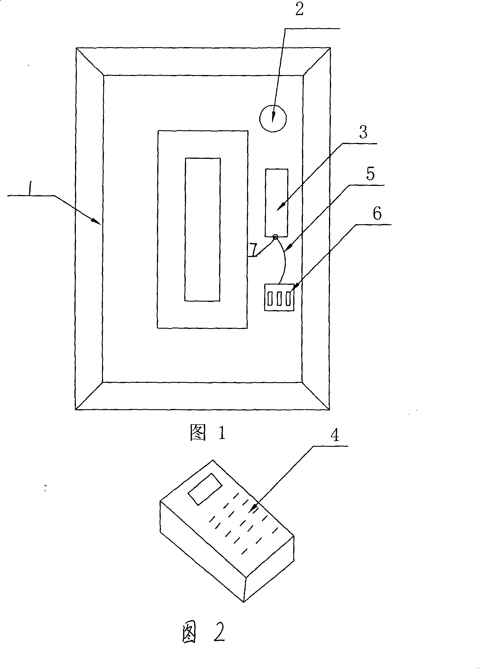
[0011] Embodiment: During installation, the door frame is installed in the wall as shown in Figure 1, one side of the door leaf is axially installed in the door frame 2, and a deadbolt groove is opened on the other side, and the lock body 3 is installed in the door frame 1 Corresponding to the dead bolt groove, when the door is closed, the dead bolt of the lock body 3 can be inserted in the dead bolt groove.

[0012] The infrared receiving light guide rod 7 is arranged beside the lock body 3 on the door frame 1 , and the infrared receiving light guide rod 7 is connected to the battery 6 through the wire 5 . A common password lock 2 is installed on the door leaf. Such electronic electronic remote control combination door lock is both safe and attractive in appearance.


PUM


Abstract

The invention relates to an electronic telecontrol password gate lock which comprises a lock body, an infrared remote controller, an infrared receiving feed rod and a power supply unit which is arranged at the lower part of the lock body, connected with the infrared receiving feed rod and composed of a conducting wire and a battery pack. The electronic telecontrol password gate lock has simple structure, convenient operation, easy execution and no hindrance during application process, can guarantee the switch performance of the electronic telecontrol lock and is convenient, safe, complete, beautiful and suitable for popularization.

Description

(1) Technical field [0001] The invention relates to a lock, in particular to an electronic remote control password door lock. (2) Background technology [0002] At present, the door locks commonly used in people's daily life are basically opened with keys, and the safety is relatively poor. Though the electronic remote control lock with infrared remote control unlocking has appeared on the market, because cost is high, price is more expensive, it is difficult to popularize and apply. (3) Contents of the invention [0003] In order to solve the deficiencies of the prior art, an electronic remote control password door lock with simple structure and convenient use is provided. [0004] The present invention is achieved through the following measures: an electronic remote control password door lock, including a lock body, an infrared remote controller, an infrared light receiving rod and a power supply device connected to the infrared light receiving rod located below the loc...

Claims


Application Information

Patent Timeline
Patent Type & Authority Applications(China)
IPC IPC(8): E05B49/00
Inventor 宋建东
Owner 宋建东
Why Eureka
Try Eureka