Reduction mechanism and switching device for switching device

A deceleration mechanism and switching device technology, applied in the direction of circuit devices, contact drive mechanisms, emergency protection devices, etc., can solve the problems of degraded transfer switch performance and service life, etc., to delay the transfer time, ensure the switching performance, and prolong the transfer time Effect

Active Publication Date: 2022-05-27
ABB (SCHWEIZ) AG
View PDF0 Cites 0 Cited by
  • Summary
  • Abstract
  • Description
  • Claims
  • Application Information

AI Technical Summary

Problems solved by technology

However, reducing the force applied to the operating mechanism may have the adverse effect of reducing the speed at which the contacts are opened and closed, which will significantly degrade the performance and service life of the diverter switch

Method used


Image

  • Reduction mechanism and switching device for switching device
  • Reduction mechanism and switching device for switching device
  • Reduction mechanism and switching device for switching device

Examples


Embodiment Construction

[0036] The subject matter described herein will now be discussed with reference to several example implementations. It should be understood that these embodiments are discussed only for the purpose of enabling those skilled in the art to better understand and thereby implement the subject matter described herein, and not for the purpose of suggesting any limitation on the scope of the subject matter.

[0037] As used herein, the term "including" and variations thereof are to be read as open-ended terms meaning "including, but not limited to." The term "based on" is to be read as "based at least in part on". The terms "one embodiment" and "an embodiment" are to be read as "at least one embodiment". The term "another embodiment" is to be read as "at least one other embodiment." The terms "first," "second," etc. may refer to different or the same object. Other definitions (explicit and implicit) may be included below. Definitions of terms are consistent throughout the specifi...


PUM


Abstract

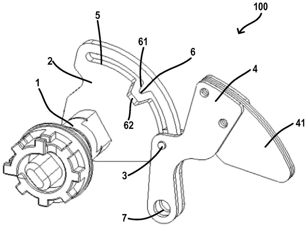
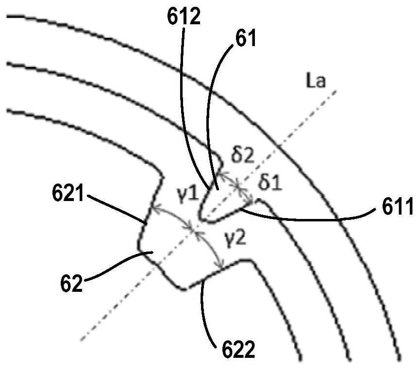
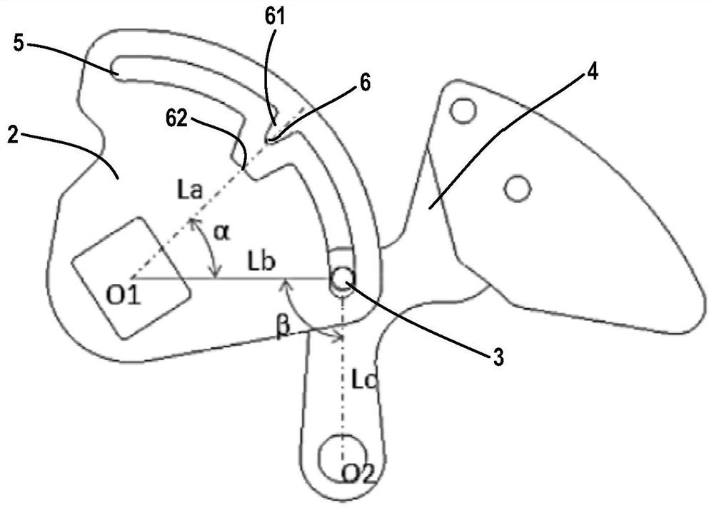
Embodiments of the subject matter described herein provide a reduction mechanism (100) for a switching device and a switching device. The reduction mechanism (100) comprises: a shaft (1) adapted to rotate in response to the operation of an actuator to drive a moving element of the switching device; at least one reduction wheel (2) fixed to the shaft ( 1) with a deceleration profile (6); and a movable rocker (4) which engages the deceleration wheel (2). The reduction wheel (2) is adapted to cause the rocker (4) to move against a reduction profile (6) on the reduction wheel (2) in response to rotation of the shaft (1) in order to decelerate the rotation of the shaft (1). The deceleration mechanism can decelerate the operation of the moving element of the switching device without affecting the switching performance and service life of the switching device.

Description

Background technique [0001] Electrical automatic transfer switches are commonly used in power distribution systems to detect and monitor power quality and to transfer power between normal and backup power sources. Depending on the application scenario, dual power automatic transfer switches are generally divided into two types, namely, two-position switches (or simply two-position switches) and three-position switches (or simply three-position switches). For three-position switches, the contacts can stop in the open position where no connection to any power source is established. For a two-position switch, the contacts only transition between the two sources, without stopping. [0002] For a two-position switch, if the contacts of the switch transition between the two positions too quickly, the contacts may touch the other power source before the arc between the contacts and the previous power source is extinguished, causing an electrical arc between the two power sources. S...

Claims


Application Information

Patent Timeline
Patent Type & Authority Patents(China)
IPC IPC(8): H01H3/32H02J9/06
CPCH02J9/06H01H3/32H01H3/42H01H3/52H01H2300/018H01H9/26H01H7/08
Inventor 林泽明
Owner ABB (SCHWEIZ) AG
Why Eureka
Try Eureka