A milling cutter head and a milling cutter tool with holow spaces for receiving a male element

A technology for milling cutters and cutter heads, applied in the field of milling cutter cutter heads and milling cutter tools with hollow spaces for receiving male elements, which can solve the problems of not being utilized

Inactive Publication Date: 2008-10-08
SANDVIK INTELLECTUAL PROPERTY AB
View PDF2 Cites 6 Cited by
  • Summary
  • Abstract
  • Description
  • Claims
  • Application Information

AI Technical Summary

Problems solved by technology

Thus, in fine milling, for example, only 1 to 10% of the entire cutting edge length is worn, leaving 90 to 99% unused

Method used


Image

  • A milling cutter head and a milling cutter tool with holow spaces for receiving a male element
  • A milling cutter head and a milling cutter tool with holow spaces for receiving a male element
  • A milling cutter head and a milling cutter tool with holow spaces for receiving a male element

Examples


Embodiment Construction

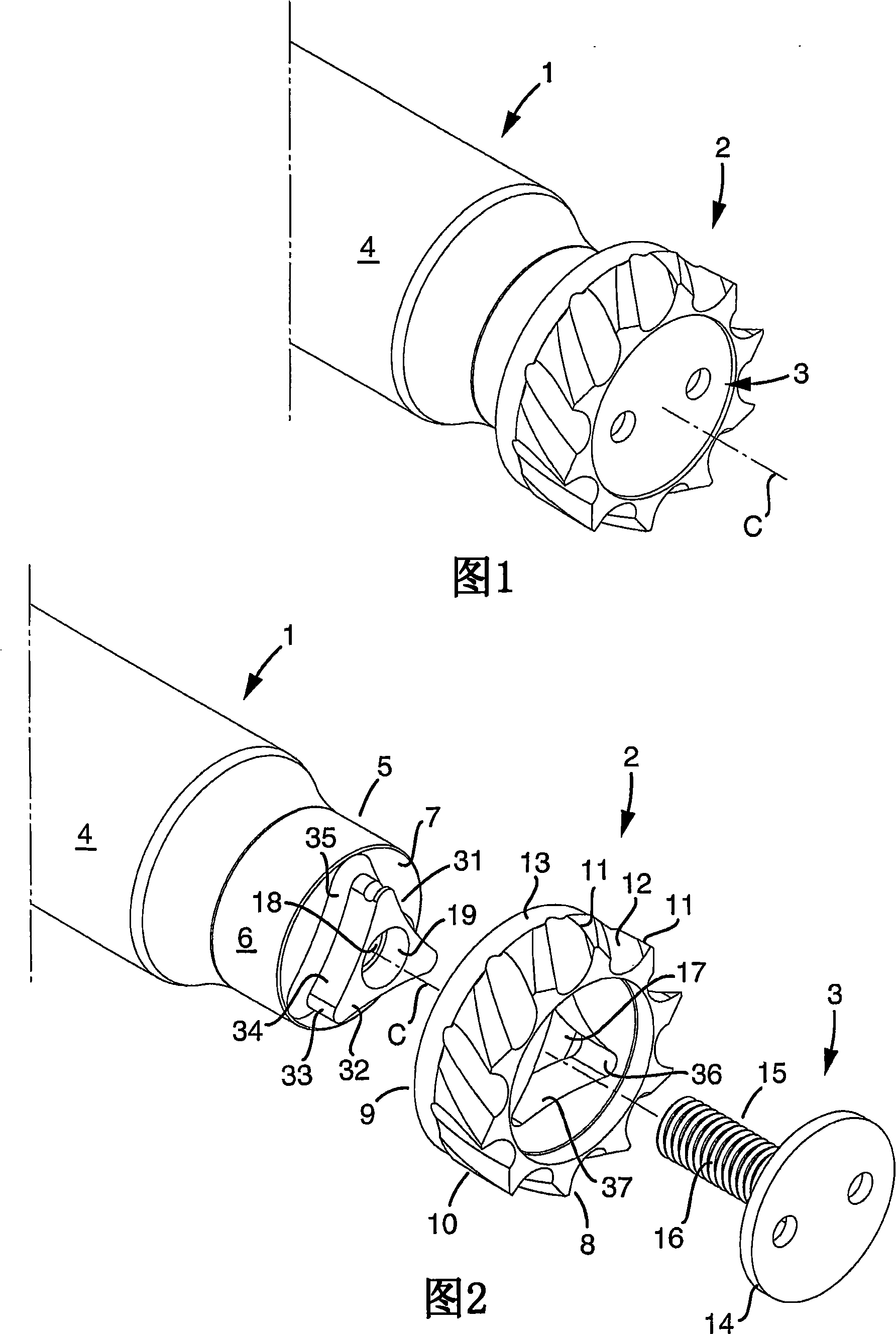
[0020] In FIGS. 1 and 2 , a milling cutter tool made according to the invention is shown, consisting of a rotatable base body 1 and a replaceable milling cutter head 2 . For fastening the milling head on the base body, fastening means 3 are used, which in the exemplary embodiment shown are in the form of front-mounted screws.

[0021] In this example, not only the milling cutter head 2 but also the basic body 1 has a rotationally symmetrical basic shape defined by a central axis C around which the tool can rotate. Advantageously, but not necessarily, the base body 1 has an elongated shape, ie, in this example, defined by a cylindrical envelope surface 4 along a substantial part of its length. At its front free end, the basic body transforms into a thinner, male element or component 5 , which is delimited by a rotationally symmetrical envelope surface 6 and a planar end face 7 . Most suitably, the envelope surface 6 is cylindrical.

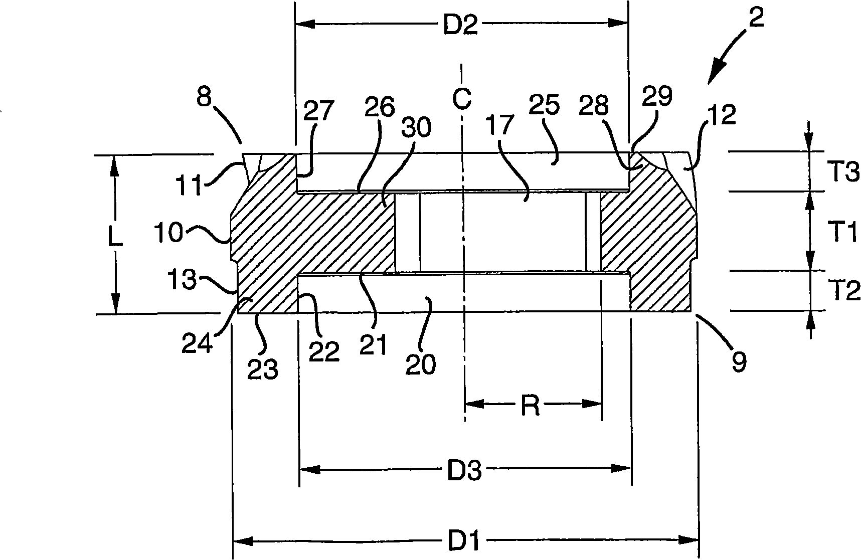
[0022] The milling cutter heads 2 each hav...


PUM


Abstract

In a first aspect, the invention relates to a replaceable milling cutter head (2), which has, on one hand, an external, rotationally symmetrical envelope surface (10) having a plurality of spaced-apart cutting edges (11) and chip flutes (12), and, on the other hand, front and rear ends (8, 9), a hollow space (20) opening in the rear end (9) of the body, and an axial hole (17) extending all the way through a frame (30) of the milling cutter head and mouthing in a bottom surface (21) in said hollow space (20). According to the invention, the milling cutter head has a flat, pulley-like basic shape so far that the axial distance (L) between the two ends (8, 9) is at most half as large as the greatest outer diameter (D1) of the body, besides which the cross-section area of the hollow space (20), in a plane perpendicular to the centre axis (C) of the milling cutter head, amounts to at least 25 % of the total cross-section area of the body, such as this is determined by said outer diameter (D1). In a second aspect, the invention also relates to a milling cutter tool having such a milling cutter head.

Description

technical field [0001] In one aspect, the invention relates to a replaceable milling cutter head, which on the one hand has an outer envelope surface having a basic shape rotationally symmetrical with respect to a central axis and comprising multiple a circumferentially spaced cutting edge and chip flute, and on the other hand having two axially spaced front and rear ends, extending all the way through the axial bore of the frame of the milling cutter head, said milling cutter The cutter head has a flat pulley-like basic shape such that the axial distance between the ends of the cutter head is at most half of the largest outer diameter of the cutter head. [0002] In another aspect, the invention also relates to a milling tool having such a milling head. Background technique [0003] In the field of milling, especially of metal workpieces, a variety of milling cutter tool solutions have recently been proposed in which the head of the milling cutter is made as a single compo...

Claims


Application Information

Patent Timeline
Patent Type & Authority Applications(China)
IPC IPC(8): B23C5/06B23C5/08B23C5/22
CPCY10T409/30952B23C5/10B23C2270/14B23C2210/02B23C2210/03B23C5/2234B23C5/06B23C5/08B23C5/22
Inventor 佩尔·布卢姆斯泰特拉尔夫·莱赫托
Owner SANDVIK INTELLECTUAL PROPERTY AB
Why Eureka
Try Eureka