Intake unit

A suction unit, suction catheter technology, used in non-displacement pumps, jet pumps, machines/engines, etc.

Inactive Publication Date: 2011-08-10
CONTINENTAL AUTOMOTIVE GMBH
View PDF0 Cites 0 Cited by
  • Summary
  • Abstract
  • Description
  • Claims
  • Application Information

AI Technical Summary

Problems solved by technology

The provision of an overflow tank is disadvantageous in that, in addition to additional material costs, production costs and installation costs, it also requires valuable installation space, which results in a burden on the usable volume in the fuel tank

Method used


Image

  • Intake unit
  • Intake unit
  • Intake unit

Examples


Embodiment Construction

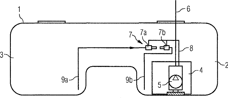
[0018] exist figure 1 The fuel tank 1 shown in has two chambers 2 , 3 separated from one another in the bottom region. A swirl box 4 with a fuel pump 5 located therein is arranged in the chamber 2 . A fuel pump 5 delivers fuel to an internal combustion engine (not shown) via a pre-pipe 6 . A suction unit 7 according to the invention is used for filling the swirl tank 4 , which consists of a first jet suction pump 7 a and a second jet suction pump 7 b. The suction unit is fastened to the swirl box 4 in the region of its upper edge. Via the working medium line 8 provided by the fuel pump 5 , the ejector pumps 7 a , 7 b are operated. Each of the jet pumps 7a, 7b has a suction duct 9a, 9b which leads into the bottom area of ​​each chamber 2, 3, so that the fuel is conveyed from the fuel tank 1 to the swirl tank 4 in.

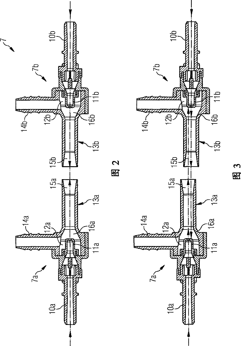
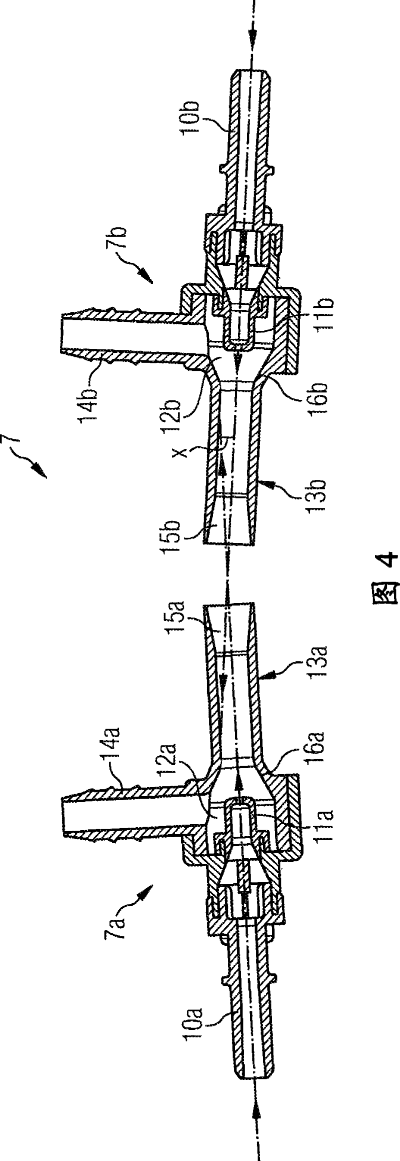
[0019] figure 2 show figure 1 The suction unit 7, but it is not fixed on the anti-swirl box. The two jet pumps 7a, 7b have the same structure. A working m...


PUM


Abstract

The invention relates to an intake unit (7), comprising an ejector pump (7a) with a propulsion jet nozzle (11a) and an ejector tube (13a). Said ejector tube (13a) has an inlet area (16a), a mixing area and an outlet area (15a). The ejector pump further comprises a pump fluid conduit (8), disposed upstream of the propulsion jet nozzle (11a), an intake area (12a), disposed between the ejector tube (13a) and the propulsion jet nozzle (11a), and an intake conduit (9a) connected to the intake area (12a). A second ejector pump (7b) is arranged relative to the ejector pump (7a) in such a manner thatboth jets of liquid exiting the respective outlet areas (15a, 15b) of the ejector tubes (13a, 13b) result in the ejector tubes (13b, 13a) of the respective other ejector pump (7b, 7a) being blocked for the passage of fluid.

Description

technical field [0001] The invention relates to a suction unit comprising: a jet suction pump with a working jet nozzle and a mixing tube, wherein the mixing tube has an inlet area, a mixing area and an outlet area; a working medium conduit arranged upstream of the working jet nozzle; a suction area between the mixing tube and the working jet nozzle; and a suction duct connected to the suction area. Such suction units are used for fuel delivery in fuel tanks. Background technique [0002] Suction units of the type mentioned at the outset have been known from the prior art for a long time. In addition to the suction unit being installed at the bottom of the fuel tank and arranged in the medium to be conveyed, there are other applications where the suction unit is arranged remotely from the medium to be conveyed, in which case one refers to the suction type ejector pumps because they have a suction line which leads from the suction area of ​​the ejector pump all the way to t...

Claims


Application Information

Patent Timeline
Patent Type & Authority Patents(China)
IPC IPC(8): F04F5/46
CPCF04F5/466
Inventor 克劳斯・马克夫卡
Owner CONTINENTAL AUTOMOTIVE GMBH
Why Eureka
Try Eureka