Polarization beam splitter and polarization conversion element
A polarization beam splitter and polarization separation technology, which is applied in the direction of polarizing elements, optical elements, instruments, etc., can solve the problems of unfavorable mass production of polarization beam splitters, high cost, etc., and achieve good polarization separation function, good polarization conversion characteristics, excellent Effect of Polarization Separation Properties
- Summary
- Abstract
- Description
- Claims
- Application Information
AI Technical Summary
Problems solved by technology
Method used
Image
Examples
example 1
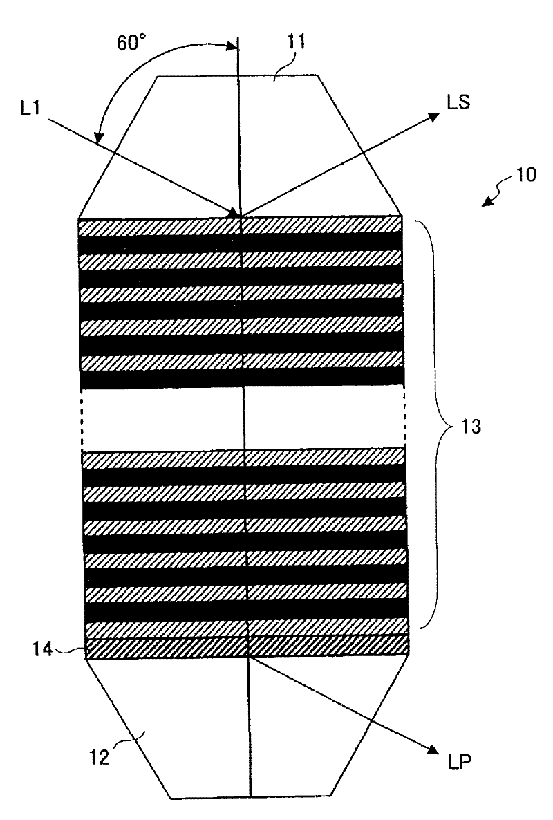
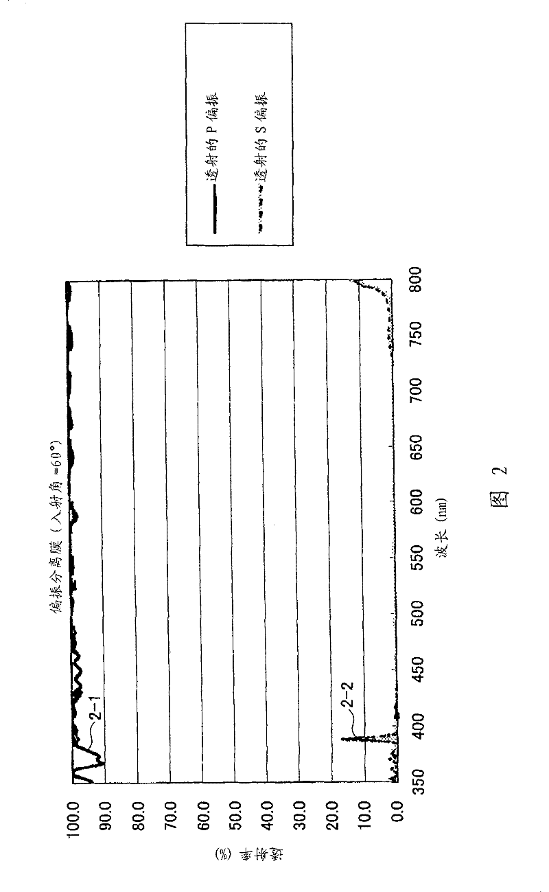
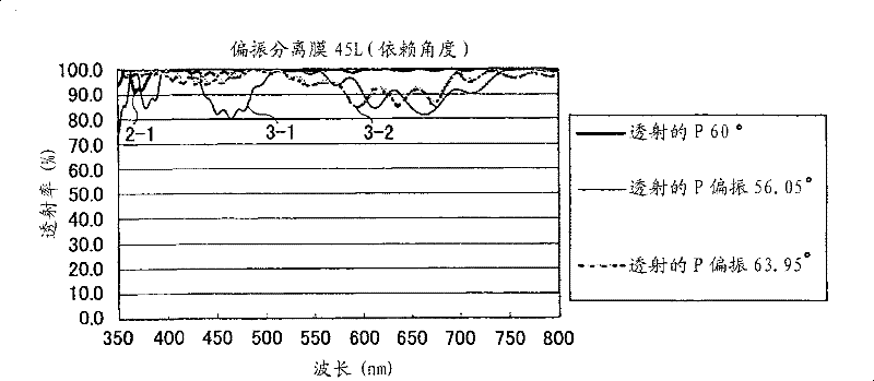
[0050] Such as figure 1 As shown, the polarizing beam splitter according to Example 1 was designed to have an angle of incidence of 60 degrees. Table 1 shows the configuration of the polarizing beam splitter according to Example 1.
[0051] (Table 1)
[0052]
[0053]
[0054] The terms in Table 1 are described below. "Layer" in the uppermost column indicates a pair of transparent substrate and dielectric film. "Substrate" in the upper part of Table 1 corresponds to figure 1 The transparent substrate 11 is shown. The "substrate" in the lower part of Table 1 corresponds to figure 1 The transparent substrate 12 is shown. Numerals 1 to 46 in the respective layers (hereinafter referred to as layer numbers 1 to 46) indicate the order of stacking the transparent substrate and the dielectric film. "Substance" means the material of the transparent substrate and the dielectric film. "Central wavelength" means the above-mentioned design base wavelength. "Refractive index"...
Deformed example 1
[0091] In Modification 1, the transparent substrate has a refractive index of 1.48 (similar to Example 1, the cross-sectional shape of the transparent substrate is a trapezoid with a base angle of 60 degrees, and the incident angle is set to 60 degrees).
[0092] Figure 4A The transmittance of P polarization (curve 4-1) and the transmittance of S polarization (curve 4-2) of Modification 1 are shown. The transmittance of P polarization is 80% or more in the wavelength range of 360nm to 800nm, and the transmittance of S polarization is substantially 0% in the wavelength range of 400nm to 800nm, which shows a good polarization separation function.
Deformed example 2
[0094] In Modification 2, the transparent substrate has a refractive index of 1.58 (similar to Example 1, the cross-sectional shape of the transparent substrate is a trapezoid with a base angle of 60 degrees, and the incident angle is set to 60 degrees).
[0095] Figure 4B The transmittance of P polarization (curve 4-3) and the transmittance of S polarization (curve 4-4) of Modification 2 are shown. The transmittance of P polarization is 80% or more in the wavelength range of 350nm to 800nm, and the transmittance of S polarization is substantially 0% in the wavelength range of 350nm to 750nm, which shows a good polarization separation function.
[0096] Next, in other modified examples of Example 1, the refractive index of the medium-refractive-index film in the first to third multilayer films was changed.
PUM
 Abstract
Description
Claims
Application Information
 - R&D
- Intellectual Property
- Life Sciences
- Materials
- Tech Scout
- Unparalleled Data Quality
- Higher Quality Content
- 60% Fewer Hallucinations
Browse by: Latest US Patents, China's latest patents, Technical Efficacy Thesaurus, Application Domain, Technology Topic, Popular Technical Reports.
© 2025 PatSnap. All rights reserved.Legal|Privacy policy|Modern Slavery Act Transparency Statement|Sitemap|About US| Contact US: help@patsnap.com


