
Eureka
For R&D, Eureka makes reading and utilizing patents & technical documents easy.
Eureka AIR
Designed for self-driven R&D workflows. Generate viable solutions, solve complex R&D challenges, empower your innovation with AI.

Eureka Materials
Designed for material experts only. Revolutionize your material R&D, from search, analyze, to developing new materials.

TechResearch
Generate reliable direction feasibility study reports for your R&D in just a few steps.

TechSeek
Discover and master advanced knowledge NOW. Basics, ideas, possibilities, all at once.

TechMind
As an expert in R&D Theories, TechMind can generates customized viable solutions instantly.

TechRisk
Analyze your overall solution with one click, know your potential R&D risks in advance.

TechMonitor
Get weekly tech updates, stay abreast of the latest tech innovations and key insights.
Battery and manufacturing method of the battery
A manufacturing method and battery technology, applied to battery pack parts, secondary battery parts, circuits, etc., can solve problems such as wrinkling of bonding parts, bad influence on battery performance, and inability to fully maintain the airtightness of battery boxes
- Summary
- Abstract
- Description
- Claims
- Application Information
AI Technical Summary
Problems solved by technology
Method used
Image

Examples
Embodiment 1
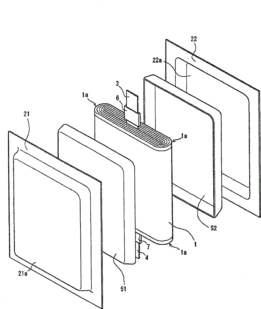
[0083] Figure 5 An exploded perspective view of the battery of Example 1 is shown in . In showing the previous battery figure 1 In the element 1 (which does not include the lead), the cups 51, 52, and the aluminum laminates 21, 22, the vertical direction (the direction in which the lead is provided) is longer than the left-right direction in the figure. However, in Embodiment 1 of the present invention, in the element 1 (which does not include lead wires), the cup-shaped covers 51, 52, and the aluminum laminated sheets 21, 22, the horizontal direction is longer than the vertical direction of the figure (the direction in which the lead wires are provided). . However, the present invention is not limited to Figure 5 In the case of element 1 etc., Figure 5 Any side length in the up-down direction and left-right direction is also acceptable.
[0084] In addition, in Example 1 of the present invention, the same as that representing a conventional battery figure 1 In compar...
Embodiment 2
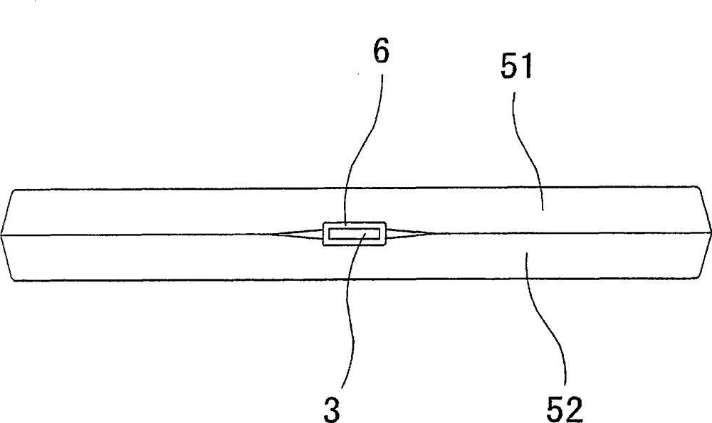
[0106]After clamping the element 1 with the cup-shaped covers 51, 52, before storing in the battery case, the four corners of the two cup-shaped covers 51, 52 are bonded with the adhesive tape 8, and the same as in Example 1, except that The battery of Example 2.
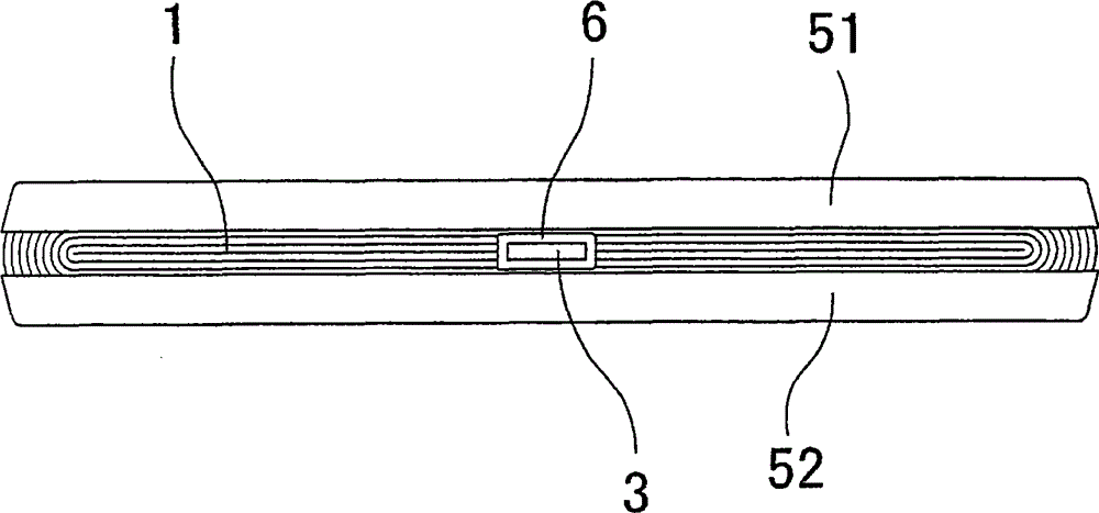
[0107] exist Figure 4 3 shows a diagram showing the four corners of the two cup-shaped covers 51 and 52 bonded with the adhesive tape 8 with the direction in which the positive electrode lead terminal 3 is drawn out as the front in the battery of Example 2. from Figure 4 It can be seen that the four corners of the two cups 51 and 52 are fixed by the tape and pressed by the adhesive tape 8 . As a result, the four corners of the two cups 51 and 52 bend and come into contact with each other. Since the central parts of the four sides of the square cups 51 and 52 are not fixed by the tape, they are not compressed like the four corners. Thus, at the central portion thereof, the two cups 51, 52 are separated from eac...
PUM
 Abstract
Description
Claims
Application Information
 - R&D Engineer
- R&D Manager
- IP Professional
- Industry Leading Data Capabilities
- Powerful AI technology
- Patent DNA Extraction
Browse by: Latest US Patents, China's latest patents, Technical Efficacy Thesaurus, Application Domain, Technology Topic, Popular Technical Reports.
© 2024 PatSnap. All rights reserved.Legal|Privacy policy|Modern Slavery Act Transparency Statement|Sitemap|About US| Contact US: help@patsnap.com