Internally guided needle

一种导向、针体的技术,应用在针织、纬编针织、经编针织等方向,能够解决增加用于针织工具的床制造复杂性、制造复杂、楔形条制造复杂等问题

Active Publication Date: 2011-04-20
GROZ BECKERT KG
View PDF1 Cites 0 Cited by
  • Summary
  • Abstract
  • Description
  • Claims
  • Application Information

AI Technical Summary

Problems solved by technology

The manufacture of wedge-shaped strips is complicated, especially because the slope is a function of the diameter of the disc or knitting cylinder
[0005] The manufacture of strips showing different slopes is complex and adds to the manufacturing complexity of the bed for the knitting tool

Method used


Image

  • Internally guided needle
  • Internally guided needle
  • Internally guided needle

Examples


Embodiment Construction

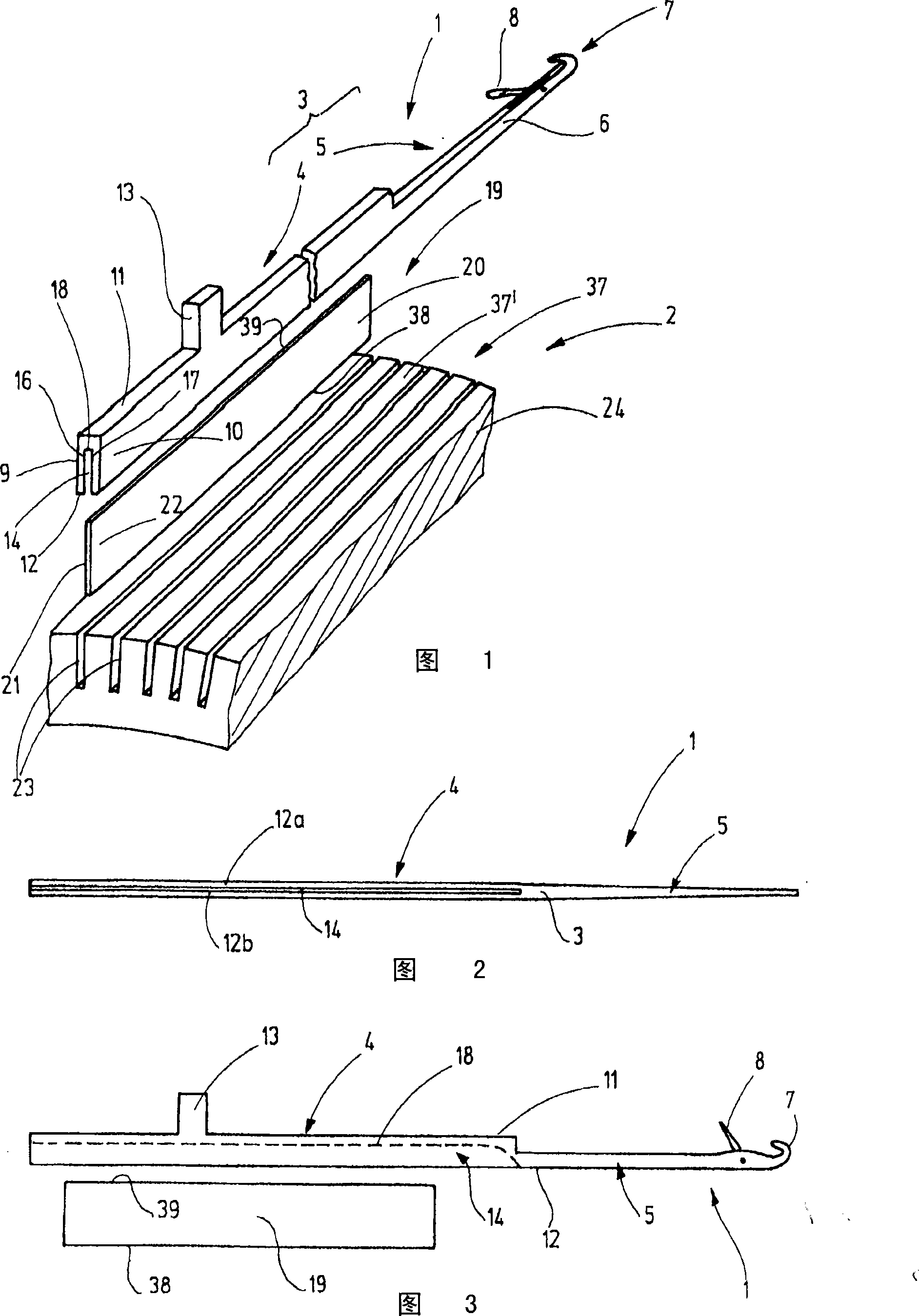
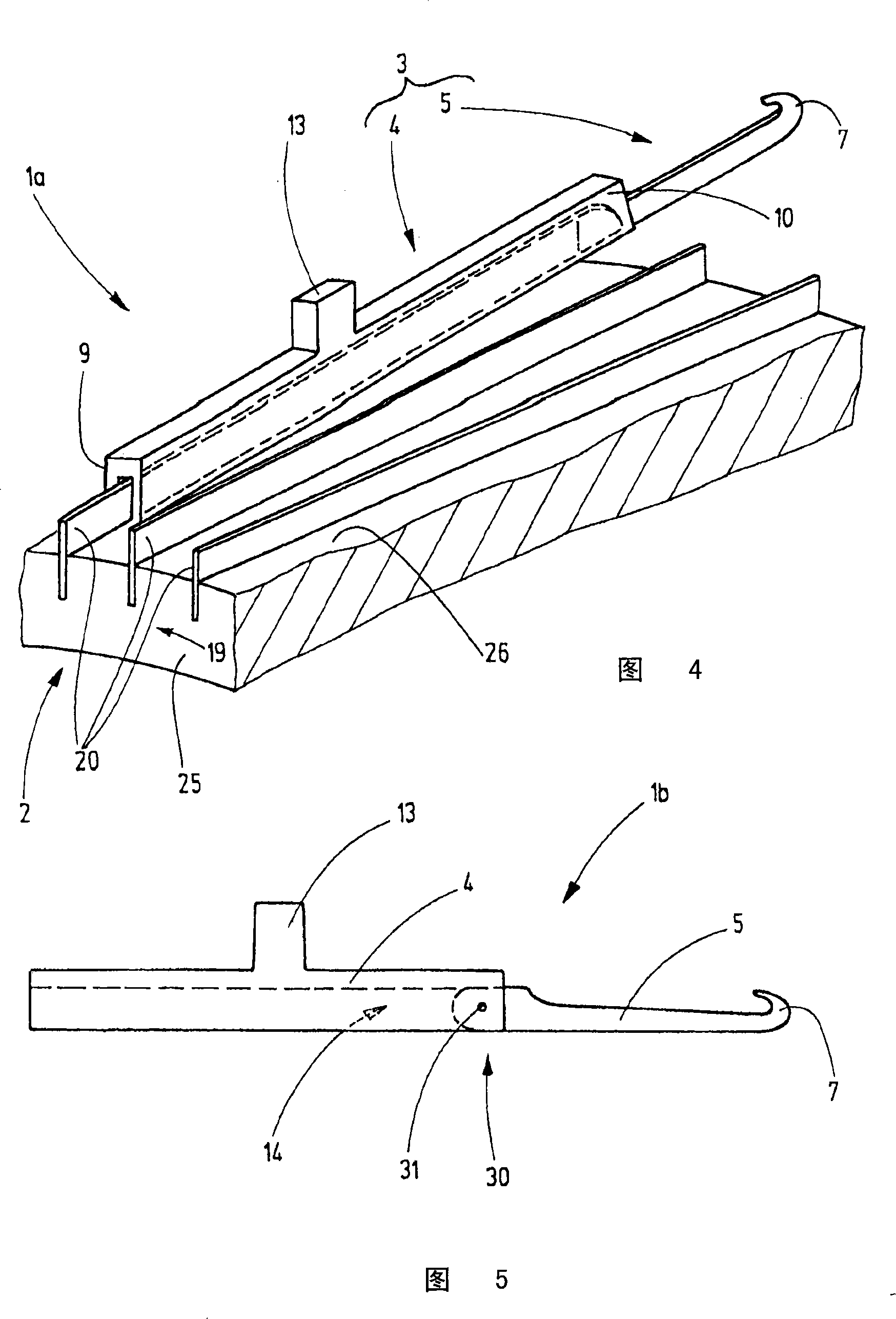
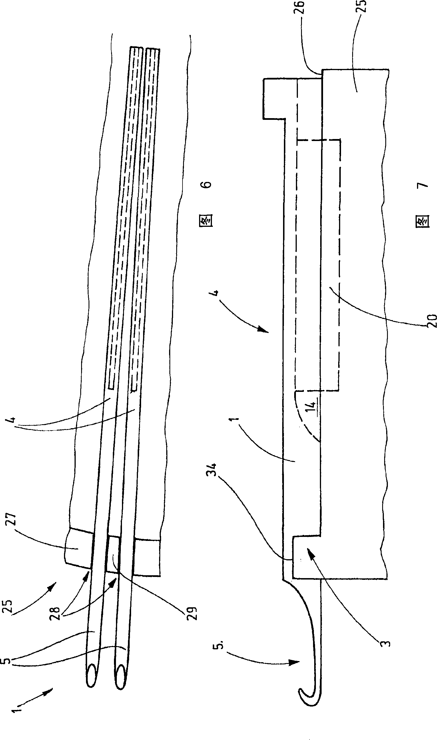
[0027] FIG. 1 shows a needle 1 and an associated needle holder in the form of a needle bed 2 . For purposes of illustration, needle 1 is a tongue needle. However, other knitting implements also exist, such as crochet hooks, transfer needles, compound needles, cutting needles, rods, and the like. The needle has a needle body 3 which is divided into a bearing part 4 and a loop forming part 5 . Referring to this exemplary embodiment, the two form a seamless one-piece unit. The loop forming part 5 extends in a straight extension from the support part 4 , like the shaft 6 . The shaft 6 has at its end a hook 7 and a closing member 8 for the hook 7 , eg in the form of a tongue, slide or the like. In the form of a tongue, the closing member 8 is supported to be pivotable towards and from the hook 7 . The tongue extends into a groove extending through the shaft 6 . However, applications are conceivable in which the knitting tool 1 does not require the closure member 8 .

[0028] ...


PUM


Abstract

The invention relates to an inner guide needle, moving vertically. According to the invention, the needle has a cannelure (14), for holding a supporting element (19) with a form of strip (20). The known needle is arranged in a guide channel and kept or inducted between two guide side parts, while the needle of the invention extends along the strip (20), for guiding on the strip. Accordingly, the needle are used to guide on the two surfaces of a guide element (19) and the strip (20), wherein the surface deviates each other. A supporting part (4) and the supporting element (19) form a locating or guiding device with high precision.

Description

technical field [0001] The present invention relates to a knitting tool for a textile machine for the production of knitted products, in particular to a knitting machine and to a needle bed associated with said knitting tool. Background technique [0002] The knitting tools are held in large numbers in suitable needle beds of the textile machine, for example in knitting cylinders or knitting disks, respectively movable in the longitudinal direction. For accommodating knitting implements such as needles, slots with a rectangular cross-section are provided in the respective beds, whereby the knitting tools are set in said slots. To create the grooves, the disc and / or the knitting cylinder is provided with grooves into which strips, preferably formed of thin steel sheets, are inserted. The gaps that exist between the strips then form channels for receiving needles or other knitting implements. To reduce wear on the groove or bar walls, the inserted bars are preferably made of...

Claims


Application Information

Patent Timeline
Patent Type & Authority Patents(China)
IPC IPC(8): D04B35/02D04B15/10D04B15/14D04B15/18D04B27/06
CPCD04B37/02D04B35/02D04B15/18D04B15/14D04B15/10D04B15/00
Inventor U·斯廷格尔
Owner GROZ BECKERT KG
Why Eureka
Try Eureka