Free access floor support and method for mounting floor using the same
A raised floor and support frame technology, applied in the field of building decoration materials, can solve the problems of waste, inconvenience, and the inability of the support frame to be accurately adjusted in height, and achieve the effect of reducing construction difficulty and facilitating installation and disassembly
- Summary
- Abstract
- Description
- Claims
- Application Information
AI Technical Summary
Problems solved by technology
Method used
Image
Examples
Embodiment 1
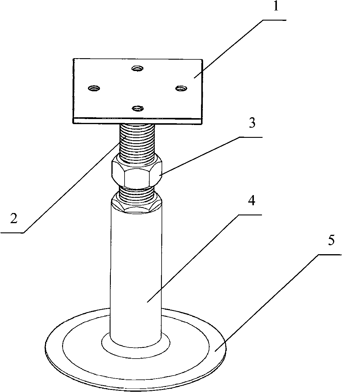
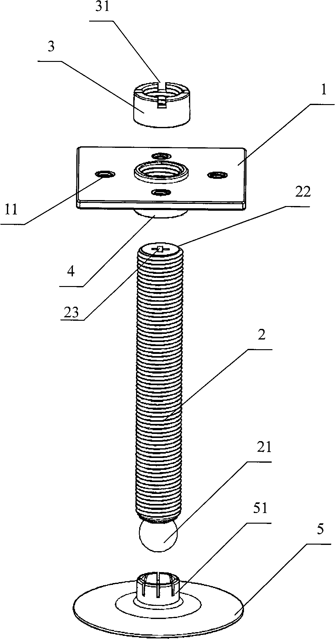
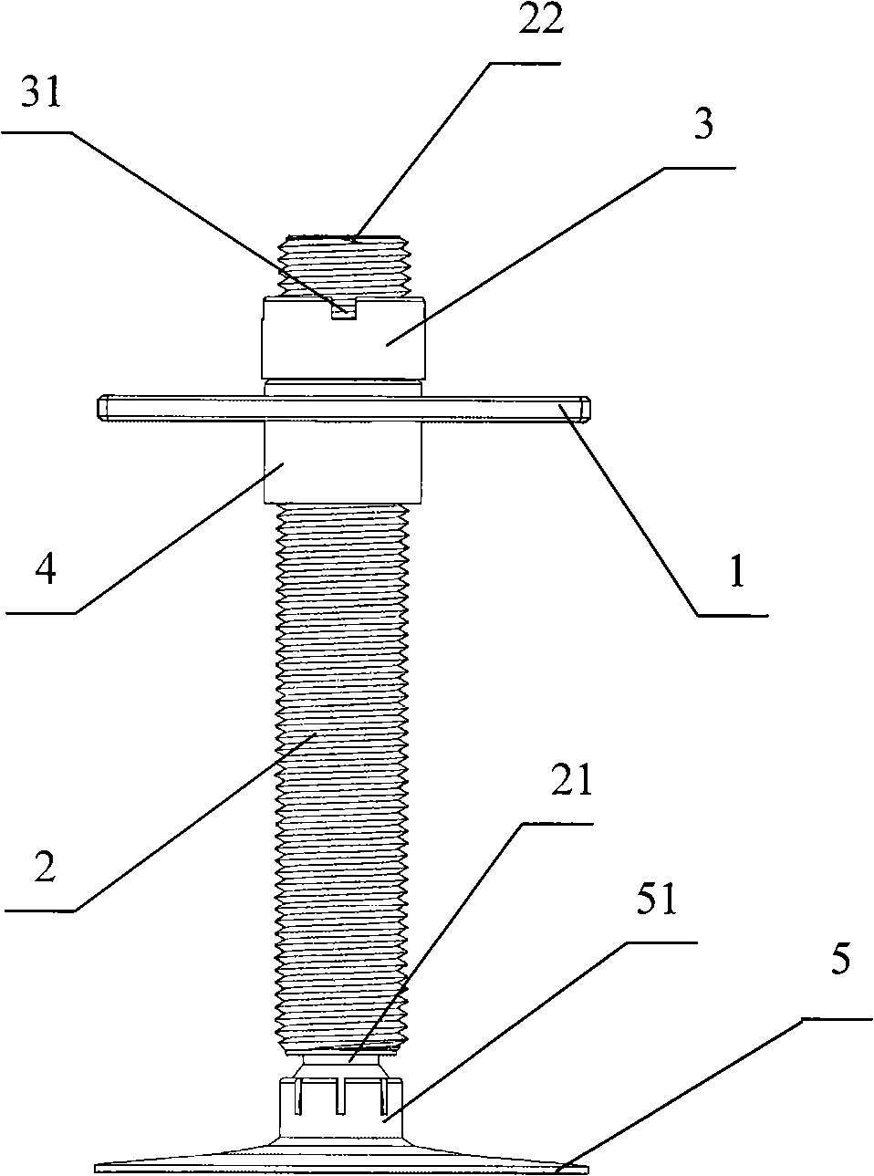
[0030] Embodiment 1, figure 2 with image 3 In combination, a raised floor support frame is provided, including a top plate 1 , a screw rod 2 , a fastening nut 3 , a threaded sleeve 4 and a base 5 . The thread on the screw rod 2 is consistent with the thread in the fastening nut 3 and the thread in the threaded sleeve 4 .
[0031] An arc-shaped concave portion 51 is fixedly arranged in the middle of the upper surface of the base 5, and the arc-shaped concave portion 51 may be an arc-shaped groove or a circular hole.
[0032] A spherical convex portion 21 matching with the arc-shaped concave portion 51 is fixedly connected to the bottom end of the screw rod 2 . The spherical convex part 21 is located in the arc-shaped concave part 51 and forms a rotational connection with the spherical convex part 21 . Such as figure 2 As shown, several passages penetrating through the circumferential surface of the arc-shaped recess 51 can be dug out, so that the arc-shaped recess 51 can...
Embodiment 2
[0038]Embodiment 2, a kind of method that utilizes the access floor supporting frame shown in embodiment 1 to carry out floor installation, at first according to the size of crossbeam 8 in the actual installation and its relation with room size; Select appropriate several sets of access floor supporting frames, Such as Figure 4 ~ Figure 6 As shown, perform the following steps in sequence:
[0039] 1. First, according to the length of the beam 8 and the connection position relationship between the beam 8 and the access floor support frame, and according to a certain interval, place the base 5 flatly on the ground.
[0040] 2. If Figure 4 As shown, first select 4 sets of movable floor support frames, and use the threaded holes 11 on the top plate 1 to install the four cross beams 8 on the upper surfaces of the four top plates 1 respectively, that is, the two ends of each cross beam 8 are respectively connected with the One top plate 1 is connected; thus, four beams 8 (togeth...
Embodiment 3
[0052] Embodiment 3. A method for floor installation using the raised floor support frame shown in Embodiment 1. First according to the size of square floor 9 in the actual installation and its relationship with room size; Figure 7 ~ Figure 8 As shown, perform the following steps in sequence:
[0053] 1. First, according to the size of the square floor 9 (the 4 corners of the square floor 9 need to open arc-shaped or square through holes) and the connection position relationship between the square floor 9 and the raised floor support frame, according to a certain interval, place the The base 5 is placed flat on the ground.
[0054] 2. If Figure 7 As shown, first select 4 sets of movable floor support frames, utilize the threaded holes 11 on the top plate 1 to install a square floor 9 on the upper surfaces of the four top plates 1 respectively, so that one square floor 9 together with the four A top plate 1 forms a mesh structure. Because the effect of the top plate 1 is ...
PUM
 Abstract
Description
Claims
Application Information
 - R&D
- Intellectual Property
- Life Sciences
- Materials
- Tech Scout
- Unparalleled Data Quality
- Higher Quality Content
- 60% Fewer Hallucinations
Browse by: Latest US Patents, China's latest patents, Technical Efficacy Thesaurus, Application Domain, Technology Topic, Popular Technical Reports.
© 2025 PatSnap. All rights reserved.Legal|Privacy policy|Modern Slavery Act Transparency Statement|Sitemap|About US| Contact US: help@patsnap.com


