Convection heater

A heater and heating element technology, applied in fluid heaters, air heaters, indirect heat exchangers, etc., can solve the problems of scrapped heaters, scrapped oil, loud noise, etc.

Active Publication Date: 2008-11-19
BASIC HOLDINGS CO LTD
View PDF0 Cites 7 Cited by
  • Summary
  • Abstract
  • Description
  • Claims
  • Application Information

AI Technical Summary

Problems solved by technology

Such heaters are particularly effective for heating small areas, but suffer from the following problems: firstly, the heat output is directed from the outlet of the heater; secondly, since they utilize fans, they are very noisy in operation
[0005] While such heaters are particularly effective for heating enclosed areas in

Method used


Image

  • Convection heater
  • Convection heater
  • Convection heater

Examples


Embodiment Construction

[0029] will now refer to figure 1 to 8 describe the present invention.

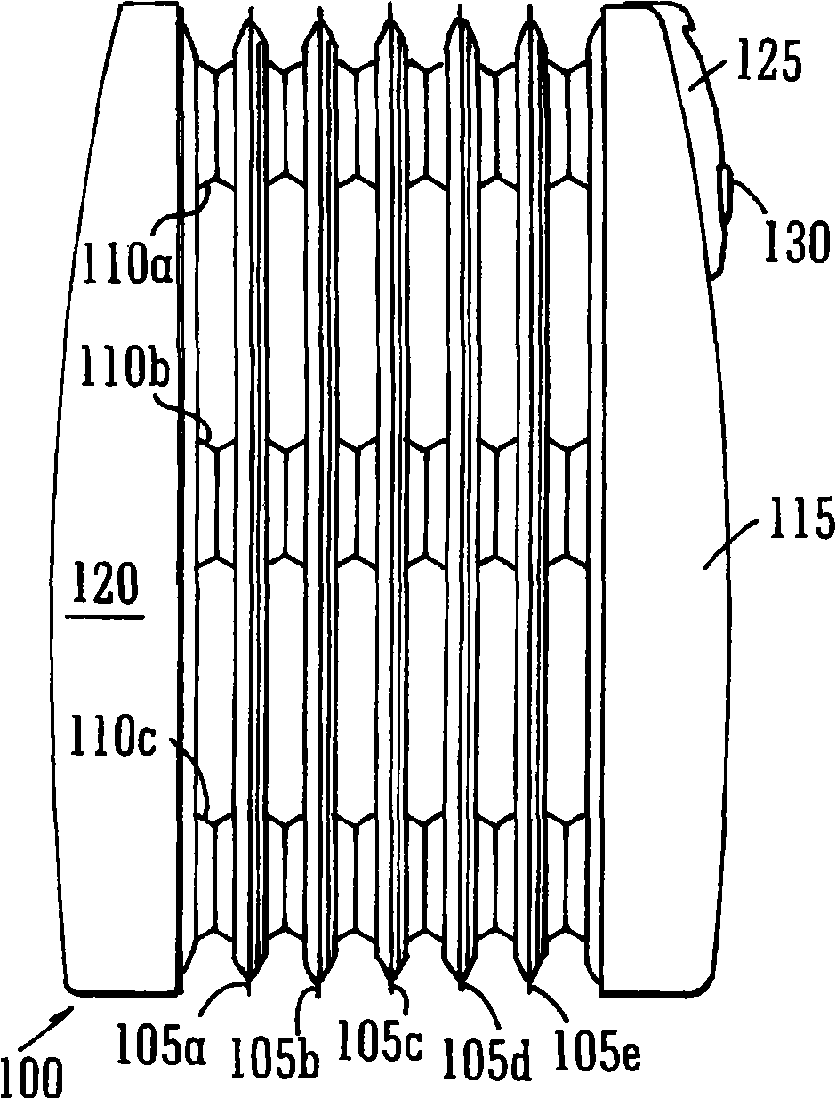
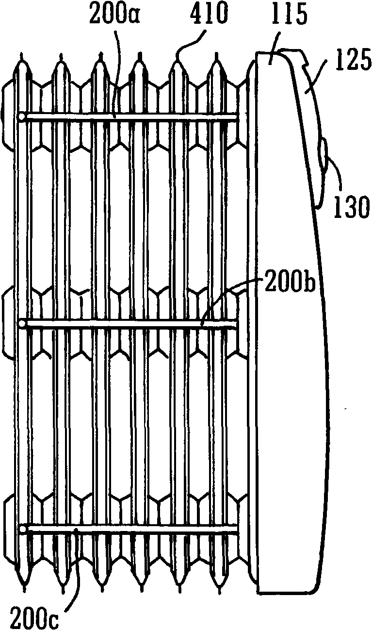
[0030] Such as figure 1 As shown in , the present invention provides a finned heater 100 comprising a plurality of vertical fins 105a, 105b, 105c, 105d, 105e arranged parallel to each other, each fin passing through at least two transverse ducts 110a , 110b, 110c are coupled to their adjacent fins, the ducts being provided with air passages between adjacent fins. by right figure 1 Upon examination, it can be seen that this exemplary embodiment includes five fins and three tubes, but this does not mean that the invention is limited to any set of values. The heater includes a first end plate 115 and a second end plate 120 . The first end plate 115 is provided with a control panel 125 which is generally conveniently located on the upper portion of the control panel to allow the user to conveniently change the temperature setting 130 on the heater without much stooping or stooping.

[0031] as passed fro...


PUM


Abstract

A heater is described which operates on the principle of convection air currents within heating fins being established by heating of air adjacent to one or more heating elements and the transfer of heat from the convection currents to the side walls of the heating fins where it may radiate outwardly as well as the direct convection of the heat from the elements in the air which passes out of the apertures at the tops of the fins into the surroundings.

Description

technical field [0001] The present invention relates to heaters, and in particular to convection heaters that utilize convection of airflow to provide heat. More particularly, the present invention relates to standalone electric domestic heaters. Background technique [0002] Domestic heaters are well known in the art. These home heaters range from heating systems that include a radiator connected to a home heating system such as a gas or oil furnace, to stand-alone heaters that are plugged in and can be used to heat localized areas of a room. Heat output from any type of heater can be due to conduction, convection or radiation or even a combination of the three. [0003] In the field of stand-alone heaters, it is known to provide fan heaters which use a heating element coupled to a fan for efficiently blowing hot air from the heater into the room in which the fan heater is placed. Such heaters are particularly effective for heating small areas, but suffer from the follow...

Claims


Application Information

Patent Timeline
IPC IPC(8): F24H3/00F28F7/02F28D1/02
CPCF24H3/002F28D1/0226
Inventor 德莫特·伦农
Owner BASIC HOLDINGS CO LTD
Why Eureka
Try Eureka