Light source scanning positioning system and its positioning method

A technology of scanning positioning and light source, applied to radio wave measurement systems, instruments, measuring devices, etc., can solve problems such as uncontrollable, unclear movement, and inability to identify the direction of movable objects, to improve the sense of direction, the positioning method is simple, low cost effect

Inactive Publication Date: 2008-12-10
LITE ON ELECTRONICS (GUANGZHOU) LTD +1
View PDF0 Cites 20 Cited by
  • Summary
  • Abstract
  • Description
  • Claims
  • Application Information

AI Technical Summary

Problems solved by technology

Since satellite signals are often not received indoors, GPS can only be used for outdoor positioning
[0003] When movable objects such as remote control cars and robots move ind

Method used


Image

  • Light source scanning positioning system and its positioning method
  • Light source scanning positioning system and its positioning method
  • Light source scanning positioning system and its positioning method

Examples


Embodiment Construction

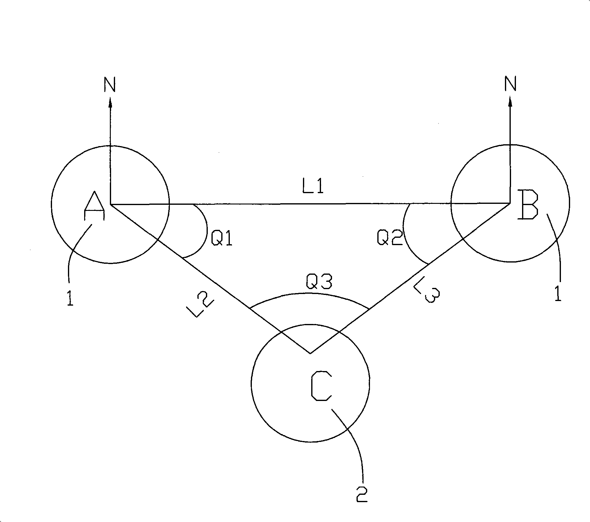
[0036] For the purpose of determining the position of the movable object, the light source receiving device is installed on a certain movable object, and the light source emitting device is a relatively fixed reference object, so as to illustrate the composition of the light source scanning positioning system:

[0037] refer to figure 1 As shown, a light source scanning positioning system includes:

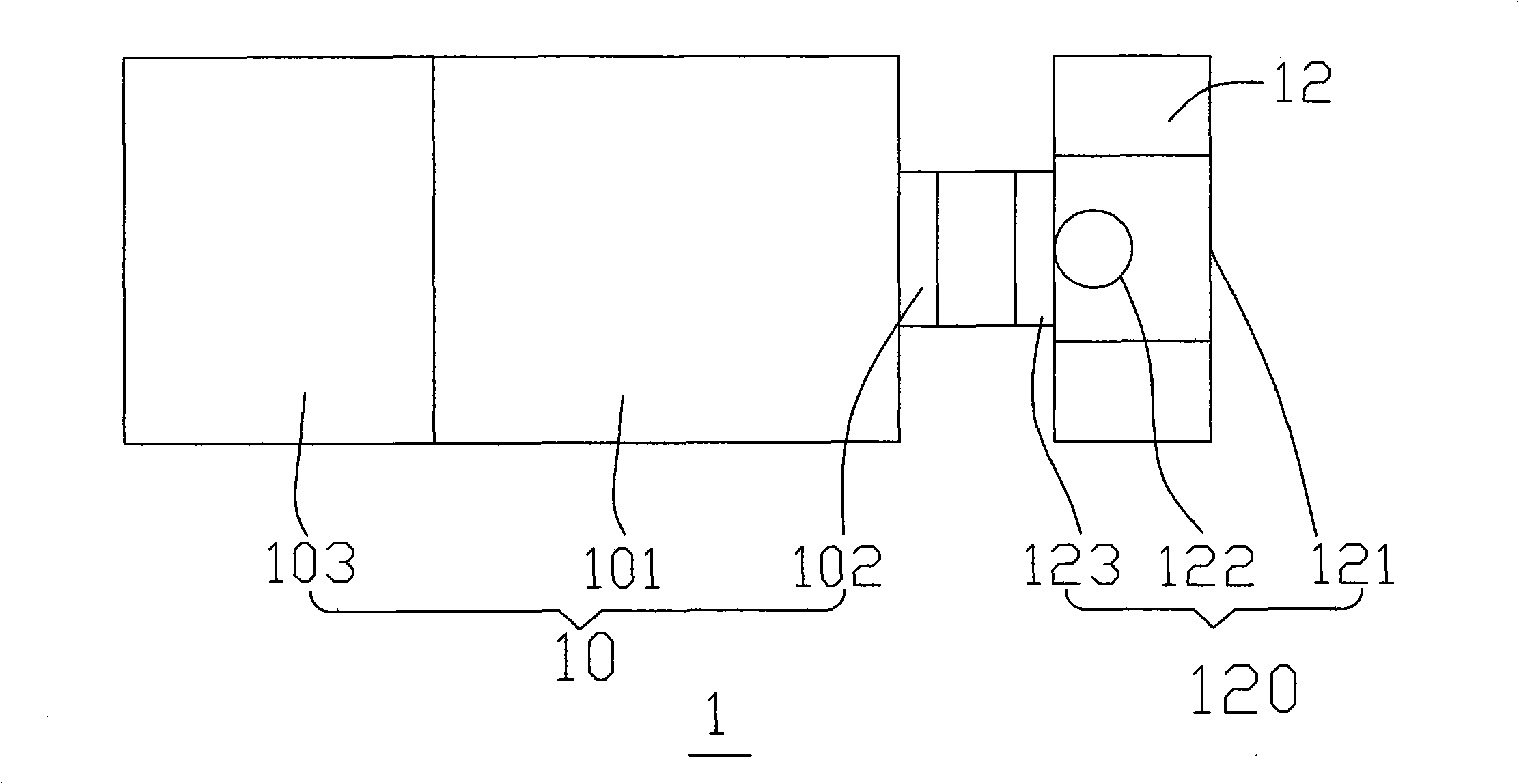
[0038] Two light source emitting devices 1 for emitting and detecting light sources;

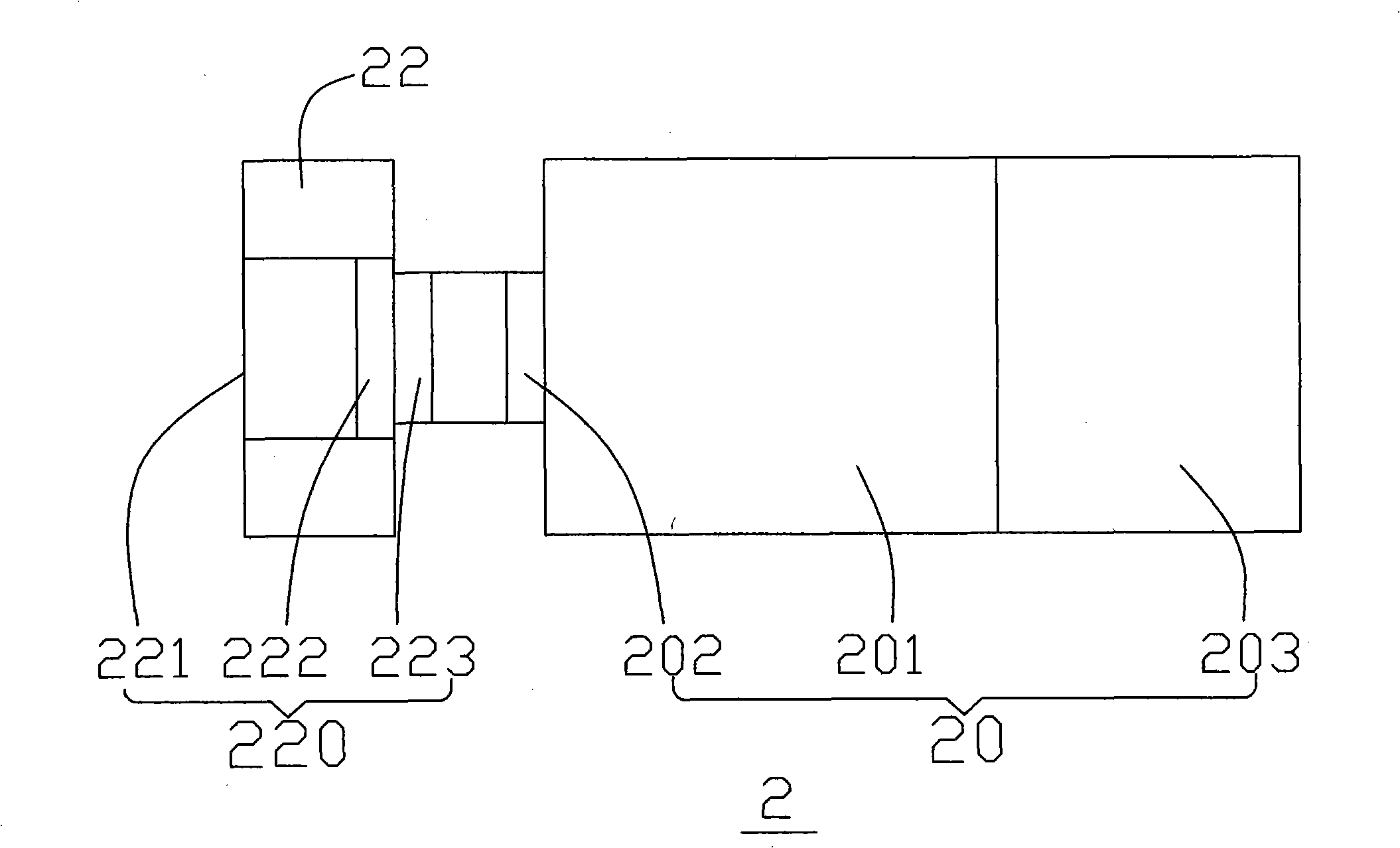
[0039] A light source receiving device 2 for receiving the detection light source;

[0040] The light source receiving device 2 includes a light source receiver and a photoelectric conversion module, and the photoelectric conversion module converts the received detection light source into an electrical signal.

[0041] Among them, by extracting the position parameters representing each light source emitting device in the electrical signal, combined with the offset angle of the light source emi...


PUM


Abstract

The invention provides a light source scanning positioning system, which comprises at least two light source emitting devices and at least a light source receiving device; wherein, the light source receiving device comprises a light signal receiver and a optical-electrical conversion module; the optical-electrical conversion module converts the received detection light source into electrical signals; the relative spaces from each of the light source emitting devices respectively to the light receiving device are calculated through extracting the position parameters of the electrical signals which characterizes each of the light source emitting devices and by combining the deviation angles of the light source emitting devices and /or the included angle information of two detection light sources and quoting the sine theorem, and thus the positions of the light source receiving devices are determined. The invention also provides a light source scanning positioning method, and the orientation of a movable object is scanned and determined through the emission and the receiving of the detection light sources; therefore the movable object can automatically distinguish the self position and automatically completes the set moving route.

Description

technical field [0001] The invention relates to a positioning system and its positioning method, in particular to a light source scanning positioning system and its positioning method which use a light source as a positioning medium to enable a movable object to automatically distinguish its own position and automatically complete a set moving route. Background technique [0002] With the rapid development of communication technology, people can use the Global Positioning System (GPS) to replace traditional paper maps to determine their location. However, the GPS system needs to rely on the satellite system for positioning, so it is often limited by the quality of the satellite reception signal. Since satellite signals are often not received indoors, GPS can only be used for outdoor positioning. [0003] When movable objects such as remote control cars and robots move indoors, if they exceed the remote control space, the movable objects are often unable to recognize the dir...

Claims


Application Information

Patent Timeline
IPC IPC(8): G01S17/50G01S17/58
Inventor 陈德宗
Owner LITE ON ELECTRONICS (GUANGZHOU) LTD
Why Eureka
Try Eureka