
Continuous heterogeneous large-area impact monitoring network and impact region positioning method

An impact monitoring and large-area technology, which is applied in the direction of using one-time impact force to test the strength of materials, can solve the problems of large additional weight of leads, reduced reliability, increased weight and power consumption, etc., achieving simple positioning methods and reducing the number of leads , the effect of improving reliability

Active Publication Date: 2018-06-15
NANJING UNIV OF AERONAUTICS & ASTRONAUTICS
View PDF9 Cites 8 Cited by
  • Summary
  • Abstract
  • Description
  • Claims
  • Application Information

AI Technical Summary

Problems solved by technology

[0006] The invention proposes a continuous heterogeneous large-area impact sensor in order to solve the problems that the large-area sensor network channel number of the intelligent skin of the aircraft leads to a large additional weight of the lead wire, an increase in the volume, weight and power consumption of the impact monitoring system, and a decrease in reliability. The monitoring network and impact area positioning method can greatly reduce the number of sensor network leads and the number of data acquisition channels of the impact monitoring system during the large-area impact monitoring of the aircraft intelligent skin, and can reduce the processor complexity of the impact monitoring system and the time required for calculating the impact position. required power consumption, thereby improving the reliability of the shock monitoring system

Method used


Image

  • Continuous heterogeneous large-area impact monitoring network and impact region positioning method
  • Continuous heterogeneous large-area impact monitoring network and impact region positioning method
  • Continuous heterogeneous large-area impact monitoring network and impact region positioning method

Examples


Embodiment Construction

[0022] The technical solution of the present invention will be described in detail below in conjunction with the accompanying drawings.

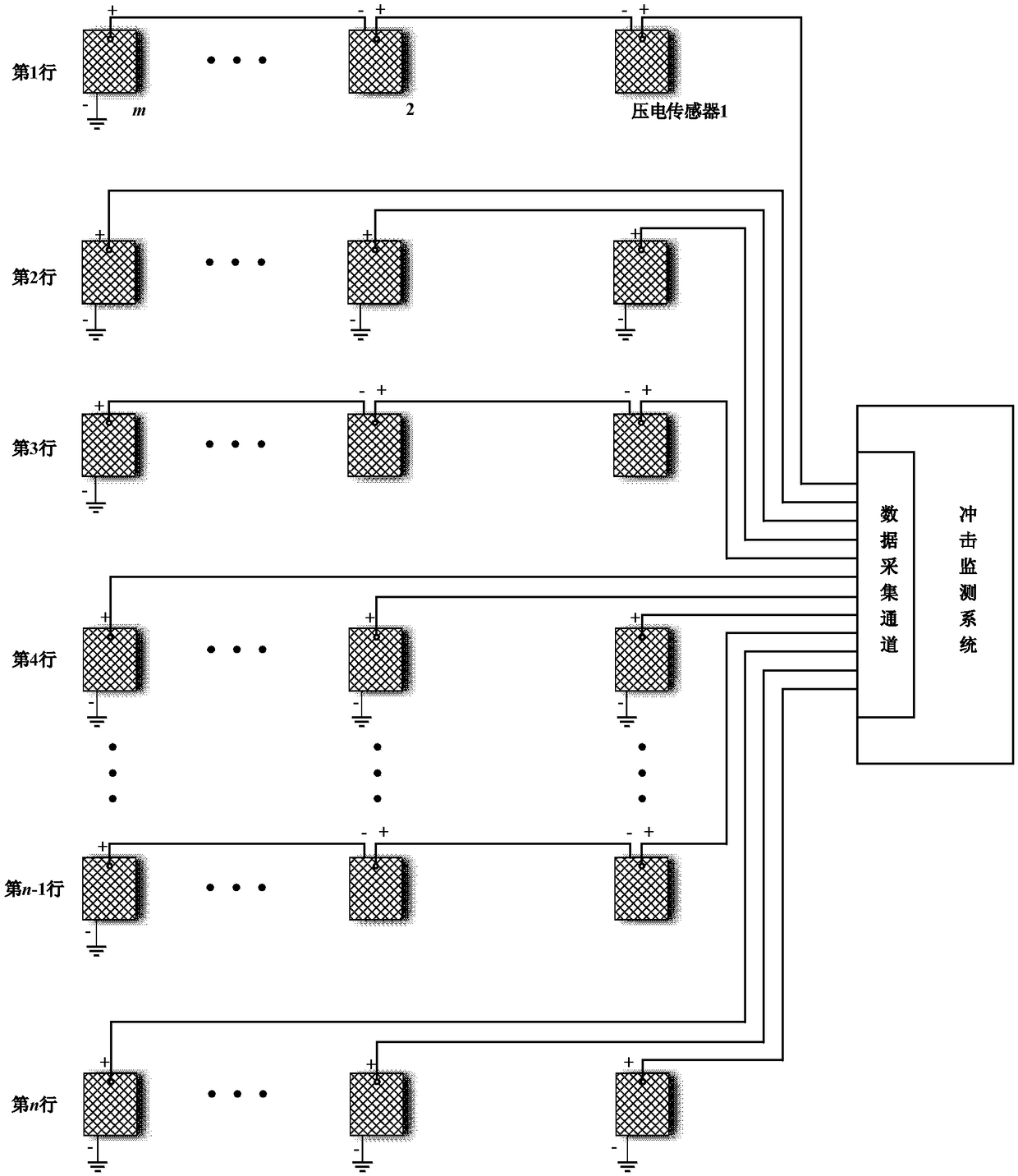
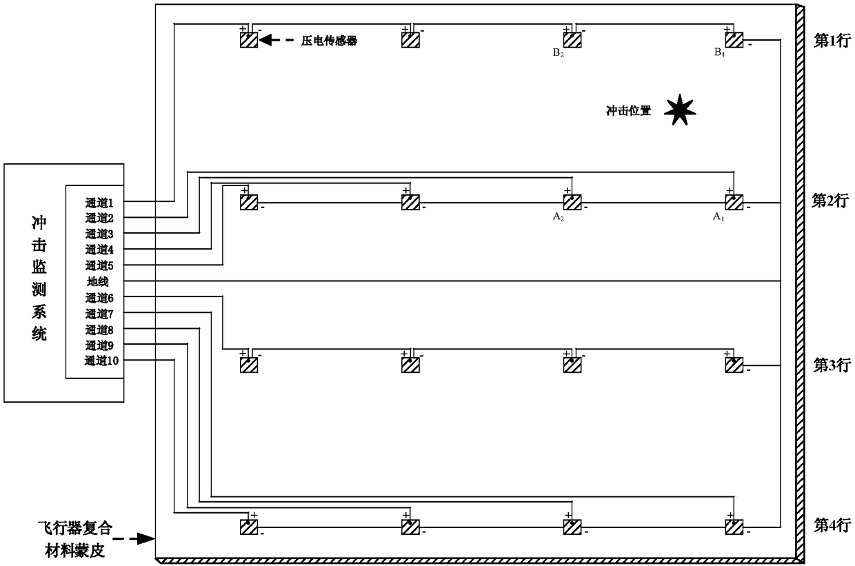
[0023] figure 1 Shown is a schematic diagram of a typical aircraft intelligent skin continuous heterogeneous large-area impact monitoring network. The entire monitoring network includes n x m A piezoelectric sensor, consisting of n Line× m columns of piezoelectric sensor arrays, where n is an even number. The entire piezoelectric sensor array is composed of a continuous series array of linear piezoelectric sensors and a discrete independent array of linear piezoelectric sensors. The first row of piezoelectric sensors forms a continuous series array of linear piezoelectric sensors, and the second row of piezoelectric sensors Form a discrete independent array of linear piezoelectric sensors, and so on, the first n-1 row of piezoelectric sensors constitutes a continuous series array of linear piezoelectric sensors, the first n The row p...


PUM


Abstract

The invention discloses a continuous heterogeneous large-area impact monitoring network and an impact region positioning method, and belongs to the technical field of aerospace intelligent structures.The continuous heterogeneous large-area impact monitoring network comprises linear piezoelectric sensor continuous series arrays and linear piezoelectric sensor discrete independent arrays which arearranged alternately, and the whole monitoring network is embedded in the interior of an aircraft composite material structure or arranged on the surface of the aircraft composite material structure to form a smart skin. When the structure is impacted by an external object, the monitoring network outputs an impulse response signal. After the impulse response signal is digitized, an impact positionis determined by an impact region positioning method. The continuous heterogeneous large-area impact monitoring network can greatly reduce the number of sensor lead wires needed for large area impactmonitoring of the smart skin of an aircraft and the number of data acquisition channels required by an impact monitoring system, can reduce the complexity of an impact monitoring system processor, reduces power required for impact position calculating so as to improve the reliability of the impact monitoring system.

Description

technical field [0001] The invention relates to a continuous heterogeneous large-area impact monitoring network and an impact area positioning method, belonging to the technical field of aerospace intelligent structures. Background technique [0002] The basic idea of ​​aircraft intelligent skin technology is to integrate a large number of sensing / driving components and microprocessors with the main skin structure as a whole, and monitor the environment, working status, health status and other information of the structure through a large number of sensing components. After processing, the control excitation is formed, and the shape, movement, and stress state of the structure are changed. Intelligent skinning technology enables the skin structure itself to have the capabilities of self-diagnosis, self-adaptation, self-learning, and self-repair. Therefore, aircraft intelligent skin technology is an important technical guarantee to improve the flight performance, operational ...

Claims


Application Information

Patent Timeline
IPC IPC(8): G01N3/30
CPCG01N3/30
Inventor 邱雷袁慎芳邓晓磊任元强
Owner NANJING UNIV OF AERONAUTICS & ASTRONAUTICS
Learn More