Underwater node positioning method oriented to sound velocity profile

A technology of sound velocity profiling and node location, which is used in the re-radiation of sound waves, the use of re-radiation, measurement devices, etc.

Active Publication Date: 2018-12-18
SHENZHEN GRADUATE SCHOOL TSINGHUA UNIV
View PDF1 Cites 5 Cited by
  • Summary
  • Abstract
  • Description
  • Claims
  • Application Information

AI Technical Summary

Problems solved by technology

[0006] The purpose of the present invention is to solve the problem of how to optimize the linear sound velocity profile algorithm and process t

Method used


Image

  • Underwater node positioning method oriented to sound velocity profile
  • Underwater node positioning method oriented to sound velocity profile
  • Underwater node positioning method oriented to sound velocity profile

Examples


specific Embodiment approach 2

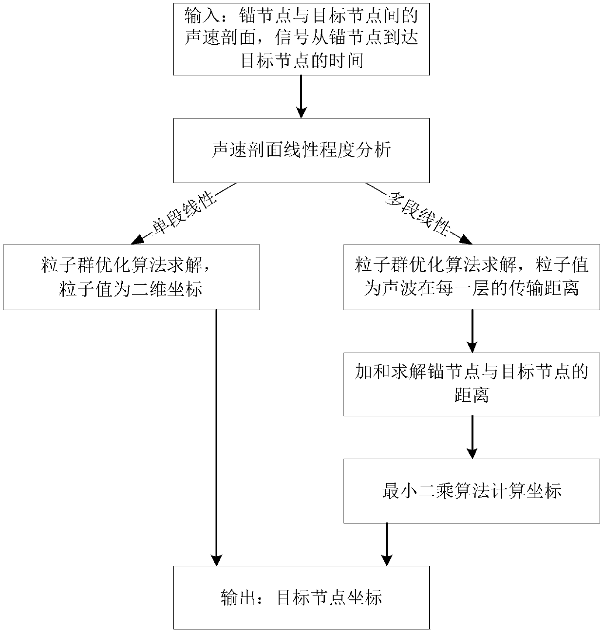
[0077] The underwater node positioning method facing the sound velocity profile of the present invention analyzes the linearity of the sound velocity profile according to the following method:

[0078] The sound velocity profile is segmented and linearized according to the degree of linearity to ensure that in each segment, the sound velocity and water depth change approximately linearly. Preferably, a greedy algorithm is used to analyze the linearity of the input sound velocity profile, which has the following steps:

[0079] (1) Initial: Assuming that the number of observed data points of the sound velocity profile is n, the entire sound velocity profile is divided into consecutive non-overlapping segments, is the round-down function. Regression lines in each segment were fitted using ordinary least squares regression.

[0080] (2) Iteration: Calculate the error increase caused by combining all adjacent segments into a regression line, and replace the two adjacent regre...

specific Embodiment approach 3

[0082] The underwater node positioning method facing the sound velocity profile of the present invention analyzes the linearity of the sound velocity profile according to the following method:

[0083] Both the anchor node and the target node are equipped with depth sensors, and the sound velocity profile linearization model to be used is determined according to the depth of the anchor node and the target node.

[0084] If the sound velocity profile between the anchor node and the target node is a single-segment linear, the single-segment linear sound velocity profile model is used;

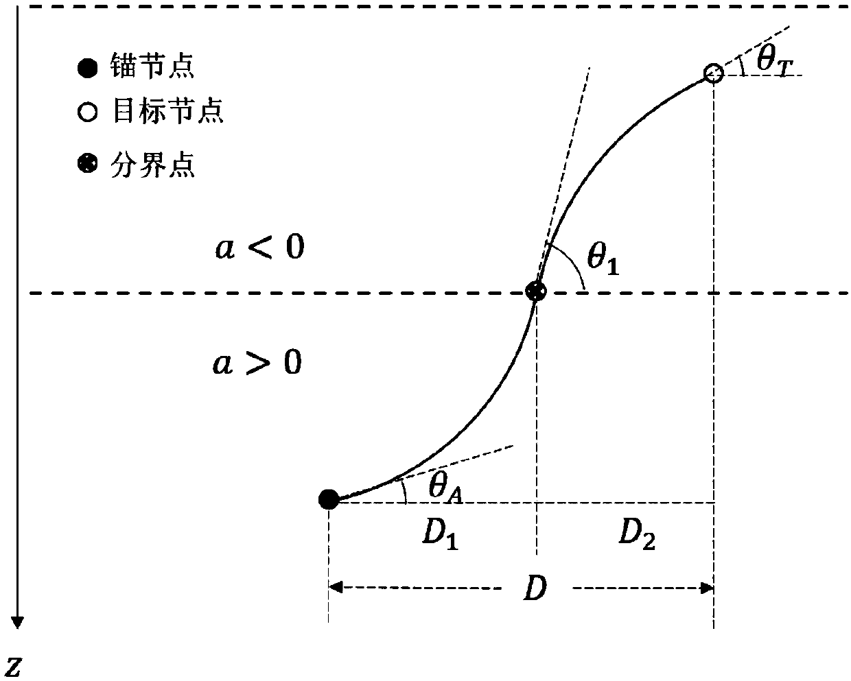
[0085] If the sound velocity profile between the anchor node and the target node is multi-segment linear, a multi-segment linear sound velocity profile model is used, and in each segment, the sound velocity and water depth change approximately linearly.

specific Embodiment approach 4

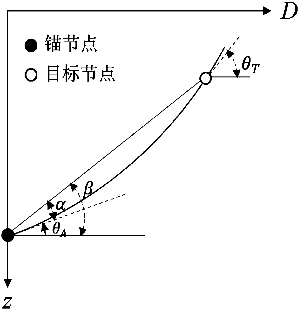
[0086] In the positioning method of the single-segment linear sound velocity profile model of the present invention, the single-segment linear sound velocity profile is as follows:

[0087] In the case of a single-segment linear sound velocity profile, when the underwater acoustic sound velocity profile is a single-segment linear, such as figure 2 shown, usually expressed as

[0088] C(z)=az+b (1)

[0089] Among them, a is the slope of the linear sound velocity profile, b is the intercept of the linear sound velocity profile, that is, the sound velocity at the horizontal plane, the sound velocity parameters a and b can be measured in advance, z is the water depth, and C(z) is the sound velocity at this depth.

[0090] Under the single-segment linear sound velocity profile, the sound propagation trajectory from the anchor node to the target node is a circular arc. Suppose a > 0, and the depth of the anchor node is greater than the depth of the target node, ie z A >z T , at...


PUM


Abstract

The invention discloses an underwater node positioning method oriented to a linear sound velocity profile. The method comprises the following steps that: A1: analyzing the linear degree of the sound velocity profile between an input anchor node and a target node; A2: according to different linear degrees, adopting particle swarm optimization; and preferably, in the A2, adopting a single-segment linear sound velocity profile model positioning method for the sound velocity profile of which the linear degree is single-segment linearity to obtain the coordinate of the target node, enabling each segment in the sound velocity profile of which the linear degree is pairwise linearity to be approximate to linear, and adopting a pairwise linear sound velocity profile model positioning method to calculate a horizontal distance between the anchor node and the target node to realize positioning. The particle swarm optimization is superior to the prior art on an aspect of performance, calculation issimplified through a segmented linear processing way, and positioning is more accurate.

Description

technical field [0001] The invention relates to the field of underwater positioning, in particular to an underwater node positioning method facing a sound velocity profile. Background technique [0002] Underwater positioning is of great significance in environmental exploration, disaster prediction, and resource development. Because the propagation distance of underwater acoustic communication is far longer than that of underwater optical communication and electromagnetic wave communication, and the technology is relatively mature, it is often used for underwater node positioning. [0003] Due to the complexity of the underwater environment, relatively accurate ranging positioning based on signal time of arrival (TOA) and ranging positioning based on signal time difference of arrival (Time Difference of Arrival, TDOA) are usually used. However, positioning based on angle of arrival (Angle of Arrival, AOA) requires additional hardware support and has a high cost; ranging po...

Claims


Application Information

Patent Timeline
IPC IPC(8): G01S15/06
CPCG01S15/06
Inventor 董宇涵孙传真李征张凯李志德
Owner SHENZHEN GRADUATE SCHOOL TSINGHUA UNIV
Why Eureka
Try Eureka