Optical disk device

An optical disc device and optical disc technology, which is applied in the recording of information on the magnetic disc, instruments, magnetic recording, etc., can solve the problems of lubricating oil leakage, attachment to the optical disc or optical disc device, oil leakage, etc., and achieve high reliability.

Inactive Publication Date: 2008-12-10
HITACHI-LG DATA STORAGE
View PDF3 Cites 2 Cited by
  • Summary
  • Abstract
  • Description
  • Claims
  • Application Information

AI Technical Summary

Problems solved by technology

[0005] However, in the optical disc device described in Patent Document 1, a hole or a recess is formed on a part of the rotor of the disc motor, and the heat generated inside the optical disc device is passed through the hole or the recess by the rotation of the rotor to dissipate the heat. The flow path, thereby allowing the heat to diffuse, can prevent the heat rise of the optical disc device, however, for improving the reliability of recording and reproduction by eliminating the pressure difference generated between the central part and the outer peripheral part of the optical disc, or in the optical disc device There is no consideration in preventing the disc from coming off when impact occurs during operation
In addition, in the optical disc device described in Patent Document 1, since the above-mentioned hole or recess is formed close to the disc motor, the oil from the disc motor leaks from the hole or recess, and may adhere to the optical disc or the optical disc device.
[0006] In addition, in the optical disc devices described in Patent Documents 2 and 3, since the above-mentioned through hole is formed close to the bearing supporting the rotating shaft of the disc motor, there is a possibility that the lubricating oil of the bearing leaks from the above-mentioned through hole and may adhere to the optical disc or the optical disc device. superior

Method used


Image

  • Optical disk device
  • Optical disk device
  • Optical disk device

Examples


Embodiment approach 1

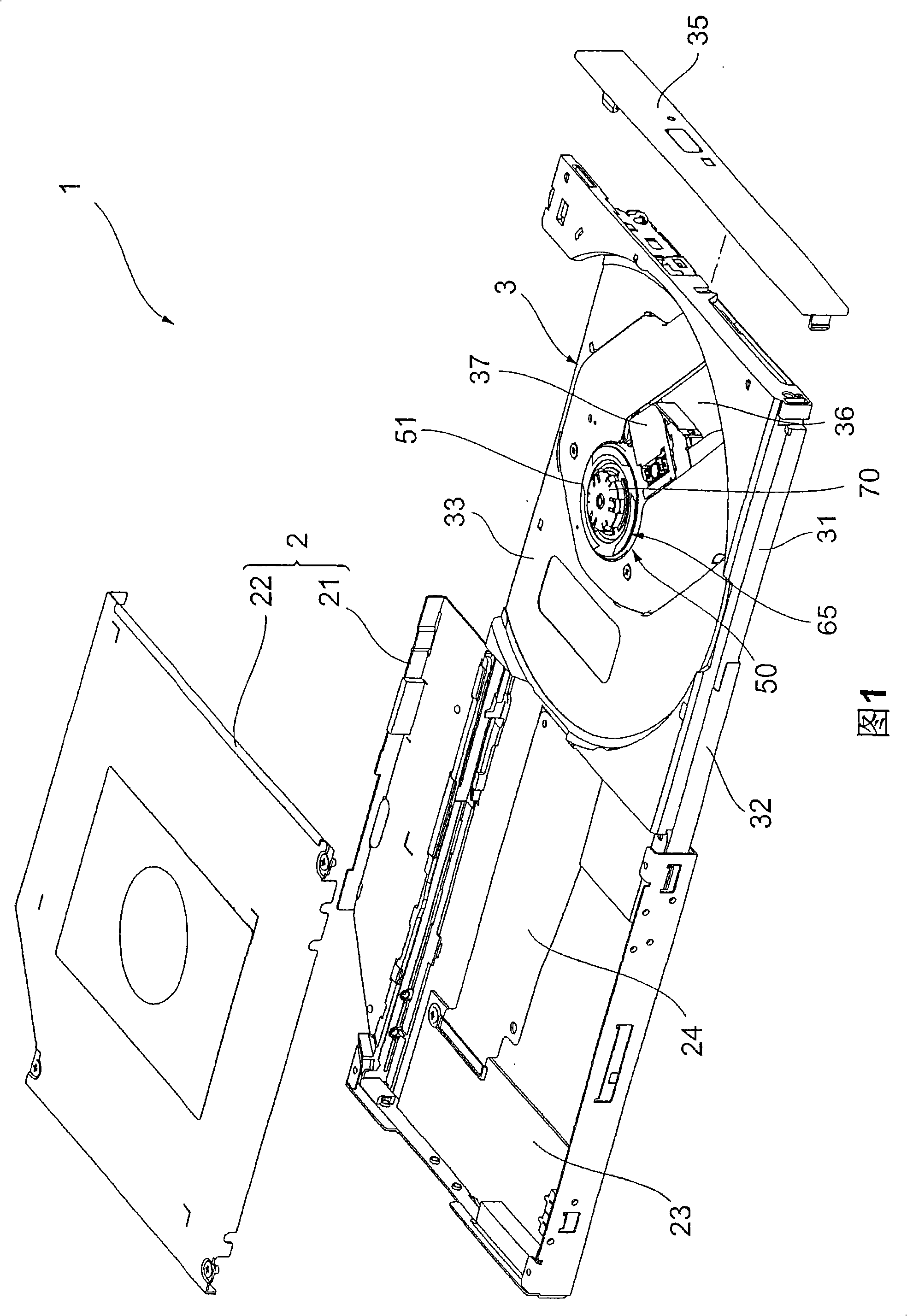
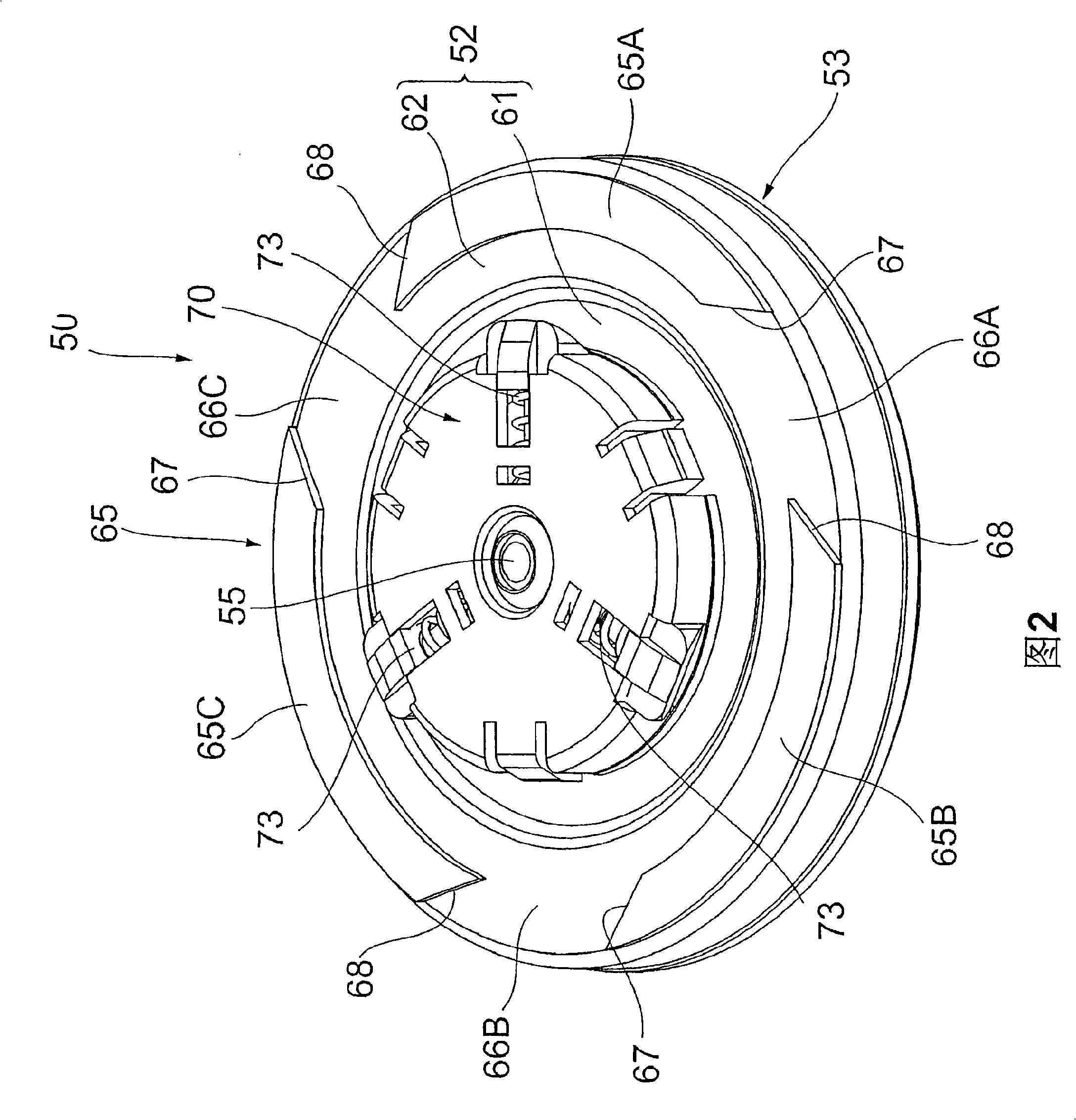
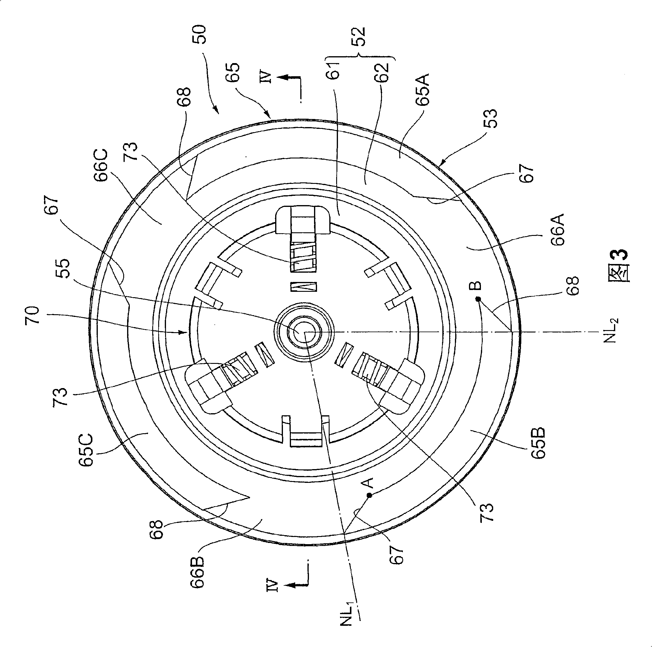
[0034] 1 is an exploded perspective view of an optical disc device according to Embodiment 1 of the present invention. FIG. 2 is a perspective view showing main parts of the optical disc device shown in FIG. 1. FIG. 3 is a cross-sectional view taken along line IV-IV, and FIG. 5 is a view showing a state in which an optical disc is mounted in the optical disc device shown in FIG. 1 on a cross-section corresponding to FIG. 3 .

[0035] In each of the above-mentioned figures, in order to facilitate understanding of the description, there are some parts where the thickness, size, magnification ratio, etc. of each member are not consistent with the actual description. In addition, the optical disk device according to Embodiment 1 will be described as a device that rotates the mounted optical disk clockwise.

[0036] As shown in FIGS. 1 to 5 , an optical disc device 1 according to Embodiment 1 includes a housing 2 and a tray 3 disposed on the housing 2 so as to be detachable. The f...

Embodiment approach 2

[0052] Next, an optical disc device according to Embodiment 2 of the present invention will be described with reference to the drawings. In the second embodiment, the same components as those in the first embodiment are denoted by the same reference numerals, and detailed description thereof will be omitted.

[0053] FIG. 10 is a perspective view showing main parts of an optical disc device according to Embodiment 2, and FIG. 11 is a plan view showing main parts shown in FIG. 10 .

[0054] As shown in FIG. 10 and FIG. 11 , the main point of difference between the optical disc device of Embodiment 2 and the optical disc device 1 of Embodiment 1 is that flow paths 166A to 166C are formed on the disc-facing surface 52 of the rotor case 53 , and flow paths 166A to 166C are formed on the disc-facing surface 52 of the rotor case 53 . An annular support member 165 is disposed on the outer peripheral portion 62 of the surface 52 .

[0055] That is, on each position of the outer perip...


PUM

PropertyMeasurementUnit
thicknessaaaaaaaaaa
thicknessaaaaaaaaaa
thicknessaaaaaaaaaa

Abstract

The invention provides a disk device that makes temperature and pressure distributed in the device even and prevents oil or lubricating oil used in the disc motor or bearing configured in the device from being attached to the disk or disk device. A restraining element (70) to be inserted into a center hole (102) in an optical disk (100) to restrain movement of the optical disk (100) in its radial direction is placed on a central portion 61 of an optical-disk-facing surface (52) of a rotor casing (53) for a disk motor (50); a supporting element (65) for supporting an optical disk surface (101) of the optical disk (100) is placed on a radially outer portion (62) of the optical-disk-facing surface (52); and flow paths (66A to 66C) are provided in the supporting element (65), and extend from the outer circumference of the supporting element (65) to its inner circumference to allow the air inside this optical disk device to flow through.

Description

technical field [0001] The present invention relates to an optical disc device, and relates to an optical disc device having a mechanism capable of uniformizing internal temperature and pressure distribution. Background technique [0002] In the prior art, as an optical disc device suitable for portable electronic devices such as personal computers or notebook personal computers, portable information terminal devices, portable image devices, etc., there are: a cover; Covered tray; a disk motor provided on the above tray to rotate the optical disc; freely movably held on the above tray, equipped with at least one optical device for recording or reproducing information on the optical disc, and approaching or leaving the above mentioned Bracket for the disc motor. In such an optical disc device, weight can be reduced by forming a hole or a recess on a part of the rotor (rotor) provided on the above-mentioned disc motor (for example, refer to Patent Document 1). [0003] In ad...

Claims


Application Information

Patent Timeline
Patent Type & Authority Applications(China)
IPC IPC(8): G11B33/14G11B17/04G11B19/20
CPCG11B17/0282G11B17/056
Inventor 深川芳弘坪田伸也
Owner HITACHI-LG DATA STORAGE
Why Eureka
Try Eureka