Photosignal waveshape recording method and apparatus

A waveform recording and optical signal technology, which is applied in the coupling of optical waveguides, wavelength division multiplexing systems, electromagnetic wave transmission systems, etc.

Inactive Publication Date: 2012-09-26
ZTE CORP
View PDF0 Cites 0 Cited by
  • Summary
  • Abstract
  • Description
  • Claims
  • Application Information

AI Technical Summary

Problems solved by technology

[0006] The technical problem to be solved by the present invention is to provide a method and device for recording optical signals, so as to solve the problem of recording optical signals in the process of production and research and development

Method used


Image

  • Photosignal waveshape recording method and apparatus
  • Photosignal waveshape recording method and apparatus
  • Photosignal waveshape recording method and apparatus

Examples


Embodiment Construction

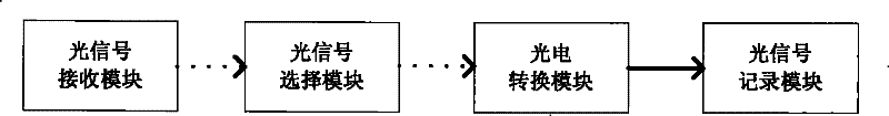
[0032] The optical signal waveform recording method of the present invention comprises the following steps:

[0033] Step 1, receiving an optical signal, including an optical signal to be recorded;

[0034] The received optical signal is a multi-channel optical signal output from the light source, and the optical signal is received at the optical fiber connection.

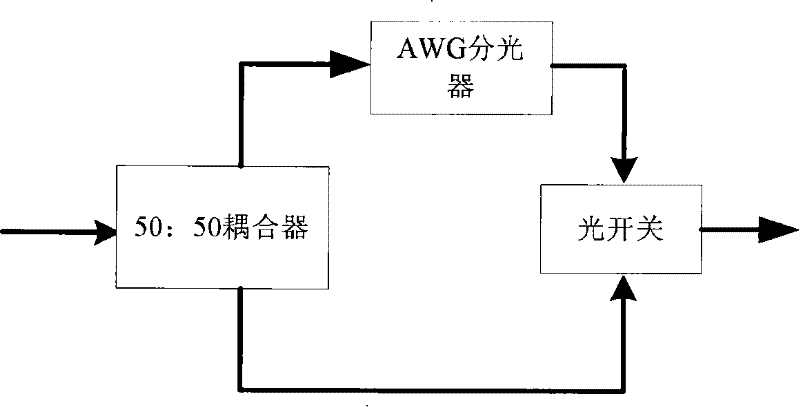
[0035] Step 2, selecting a specific optical signal to be recorded from the received optical signals;

[0036] Select the optical signal to be recorded, and select different optical signals according to different requirements, and input them into the photoelectric conversion circuit.

[0037] The selected specific optical signal may be an optical signal of a specific wavelength or an optical signal of all wavelengths.

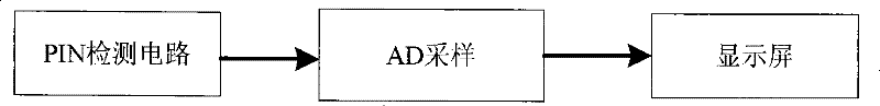
[0038] Step 3, converting the optical signal to be recorded into an electrical signal;

[0039] The optical signal to be recorded is processed, mainly through photoelectric conversion to generate ...


PUM


Abstract

An optical signal waveform recording device comprises an optical receiving module, an optical signal selecting module, an optoelectronic switching module and an optical signal recording module, wherein the optical receiving module, the optical signal selecting module and the optoelectronic switching module are connected in turn through an optical path, and the optoelectronic switching module and the optical signal recording module are connected through a circuit. The optical receiving module is used for receiving the optical signal, including the optical signal to be recorded; the optical signal selecting module is used for selecting the optical signal to be recorded from the received optical signal; the optoelectronic switching module is used for switching the optical signal to be recorded into the optical signal through the optoelectronic switching circuit; the optical signal recording module is used for recording the electrical signal. The inside of the device can be arranged with different optical signal selecting sub-devices, thereby supporting the recording of a plurality of optical signals.

Description

technical field [0001] The invention relates to a DWDM system, in particular to a method and a device for recording an optical signal waveform. Background technique [0002] Dense Wavelength Division Multiplexing (DWDM) is a broadband optical transmission technology that multiplexes multiple optical signals of different wavelengths for transmission, and then demultiplexes the multiple optical signals in the optical fiber after transmission, and sends them to different communication channels. The terminal provides multiple virtual fiber channels on one physical fiber, thus saving a lot of fiber resources. Observing and recording optical signals has become a key and important technology in DWDM technology. [0003] Requirements for optical index testing work: [0004] In the production of WDM product optical circuit boards, multiple optical indicators need to be tested. Different boards have different test environments and methods, and different test environments need to be...

Claims


Application Information

Patent Timeline
Patent Type & Authority Patents(China)
IPC IPC(8): H04J14/02H04B10/08G02B6/42
Inventor 阎大海
Owner ZTE CORP
Why Eureka
Try Eureka