Clamping beam

A technology of clamping parts and tools, applied in the direction of forming tools, sleeve/socket connections, mechanical equipment, etc., can solve the problems of not being able to obtain directly frequently, increasing costs, etc.

Active Publication Date: 2008-12-17
WILA
View PDF0 Cites 4 Cited by
  • Summary
  • Abstract
  • Description
  • Claims
  • Application Information

AI Technical Summary

Problems solved by technology

[0008] A disadvantage of systems using pressurized air or hydraulic fluid is that a compressor is required to provide the pressurized air or hydr

Method used


Image

  • Clamping beam
  • Clamping beam
  • Clamping beam

Examples


Embodiment Construction

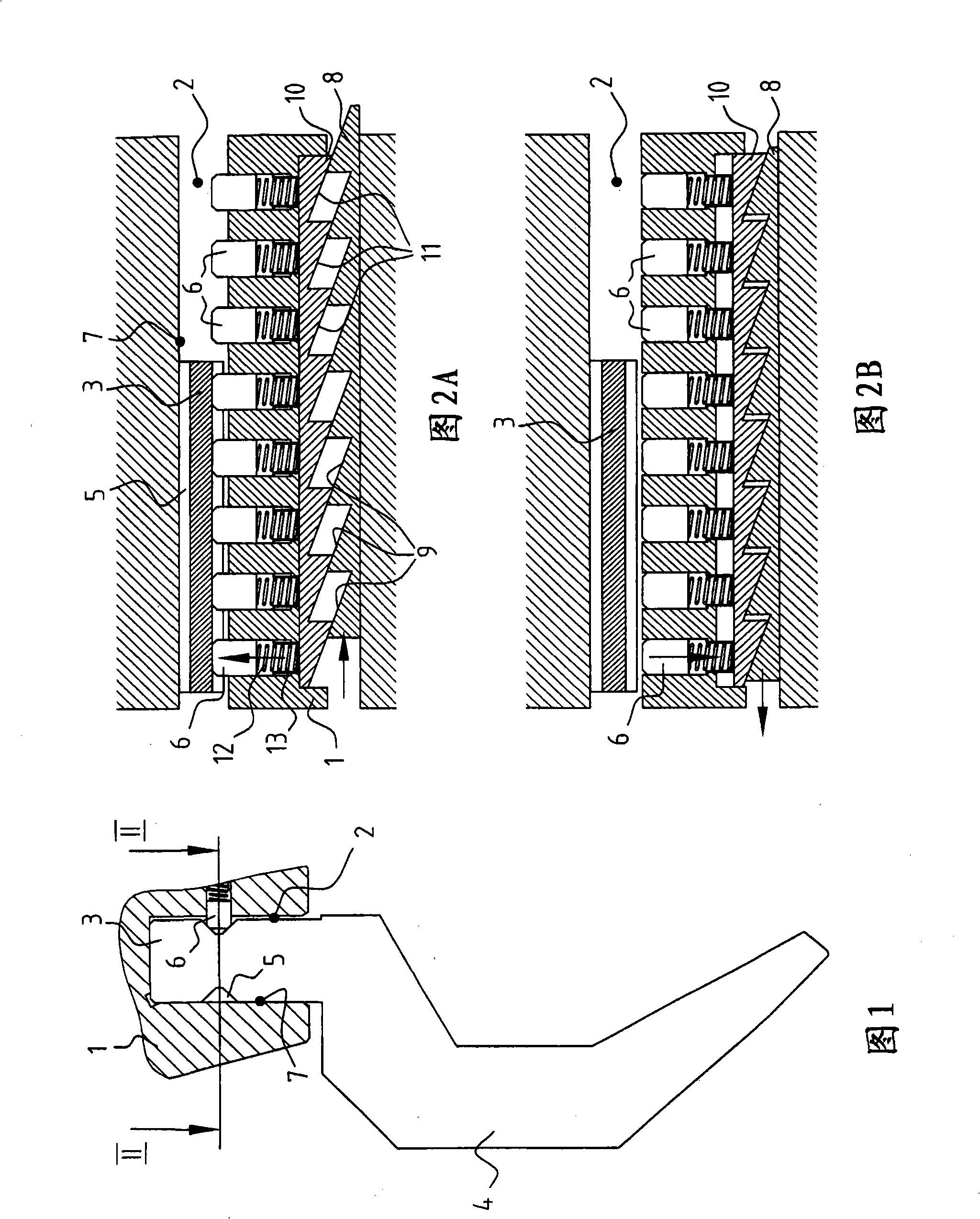
[0043] FIG. 1 shows a cross-sectional view of a clamping system 1 with a groove 2 in which a clamping part 3 of a tool 4 is arranged. The clamping part 3 of the tool has a V-shaped recess 5 into which a pin 6 is pushed to clamp the tool 4 . The pin 6 extends into the groove 2 , with the result that the clamping portion 3 is pushed against the wall 7 of the groove 2 .

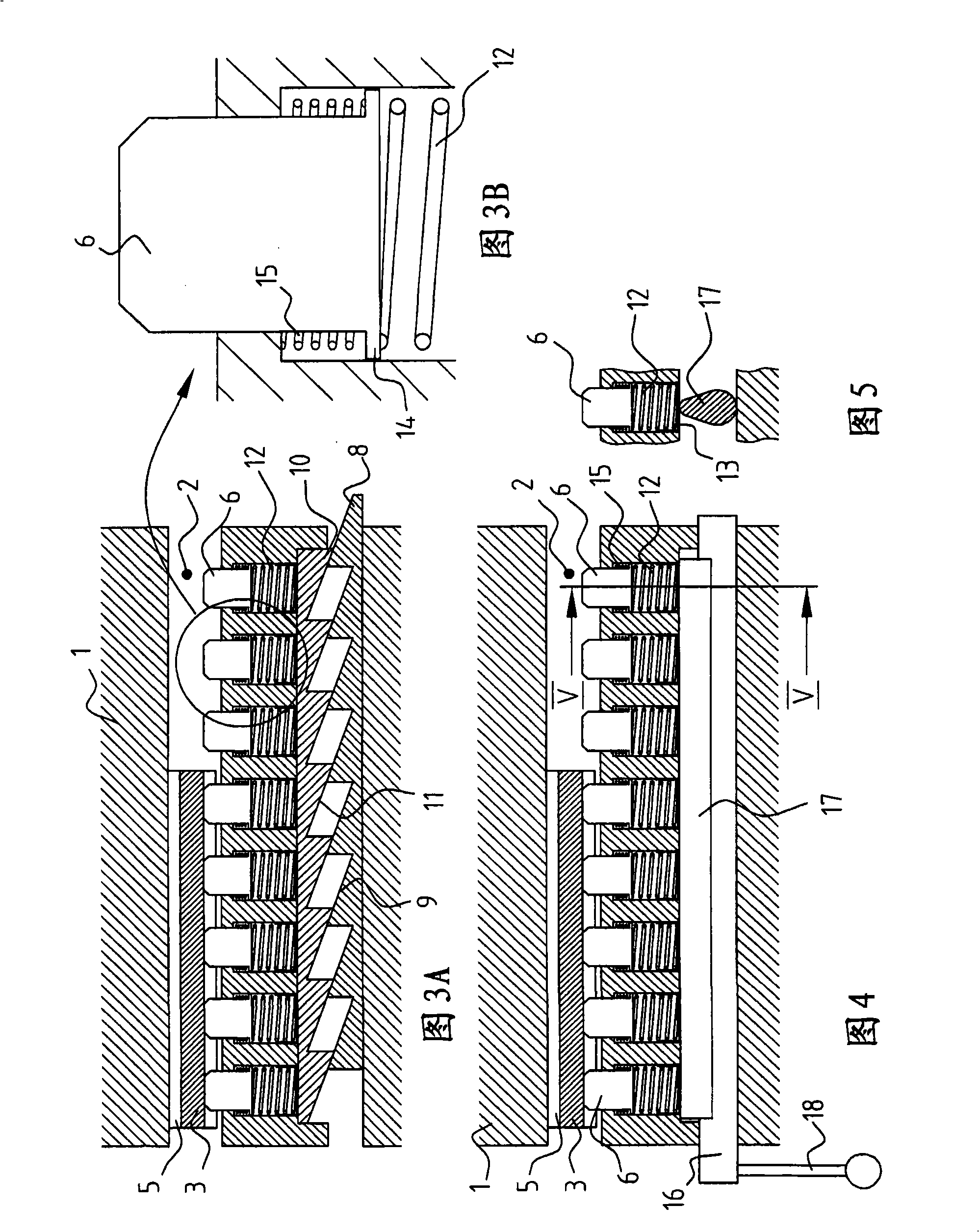
[0044] FIG. 2A is a cross-sectional view along line II-II in FIG. 1 . The pin 6 is introduced into the body of the clamping system 1 . In the clamping system 1 , a first frame 8 with a slope 9 is slidably disposed in the clamping system 1 . A second frame 10 with a ramp 11 is adjacent to said frame 8 so that said ramps 9 and 11 work together. As shown in Figure 2A, by moving the frame 8 to the right, the frame 10 is laterally pushed away, resulting in the extension of the pin 6 into the groove 2, thereby clamping the tool 4 clamping part 3.

[0045] Each pin 6 is part of a pusher element. This pushing elem...


PUM


Abstract

The invention relates to a clamping system for clamping a plurality of tools, wherein the system comprises: a body; an elongated groove (2) arranged in the body for reception of a clamping part of at least one tool; at least one pusher element extendable into the groove for pushing the clamping part of a tool against a wall of the groove; wherein, shape imposed displacement means for displacing the at least one pusher element from a first position substantially freeing the groove, enabling insertion of the clamping part of the tool into the groove, towards a second position, in which the at least one pusher element extends into the groove.

Description

technical field [0001] The invention relates to a clamping system for clamping a plurality of tools, wherein the system comprises: [0002] main body; [0003] an elongated recess disposed within the body for receiving the gripping portion of at least one tool; [0004] At least one urging element extendable into the groove for urging the clamping portion of the tool against at least one wall of the groove in at least one direction. Background technique [0005] Such clamping systems are known, for example, for bending machines, such as press brakes, rotary benders, or folding machines. Typically the tool is inserted into the clamping system of the bending machine and the tool is clamped in the clamping system. For clamping the clamping part of the tool, a pusher element projects into the groove to push the clamping part of the tool against the groove wall and thereby be clamped. The force required to cause the pusher element to protrude into the groove is typically prov...

Claims


Application Information

Patent Timeline
IPC IPC(8): B21D37/04B21D5/00
CPCB21D5/0209Y10T279/1973Y10T279/17811Y10T279/1961Y10T279/19Y10T279/29
Inventor F·W·鲁韦勒
Owner WILA
Why Eureka
Try Eureka