
Screw nail

A screw and screw rod technology, applied in the direction of screws, threaded fasteners, connecting components, etc., can solve problems such as insufficient continuation function, and achieve the effects of labor-saving operation, stable locking, and rapid chip removal.

Inactive Publication Date: 2008-12-17
徐国泰
View PDF1 Cites 1 Cited by
  • Summary
  • Abstract
  • Description
  • Claims
  • Application Information

AI Technical Summary

Problems solved by technology

[0004] However, when the inventor used the screw of the aforementioned patent in actual use, he found that the height of the convex rib located between the screw thread and the screw shaft must be lower than the thread thread, which makes it slightly insufficient in the continuation function of chip removal. room for improvement

Method used


Image

  • Screw nail
  • Screw nail
  • Screw nail

Examples


Embodiment Construction

[0023] Specific embodiments of the present invention are described below in conjunction with accompanying drawing:

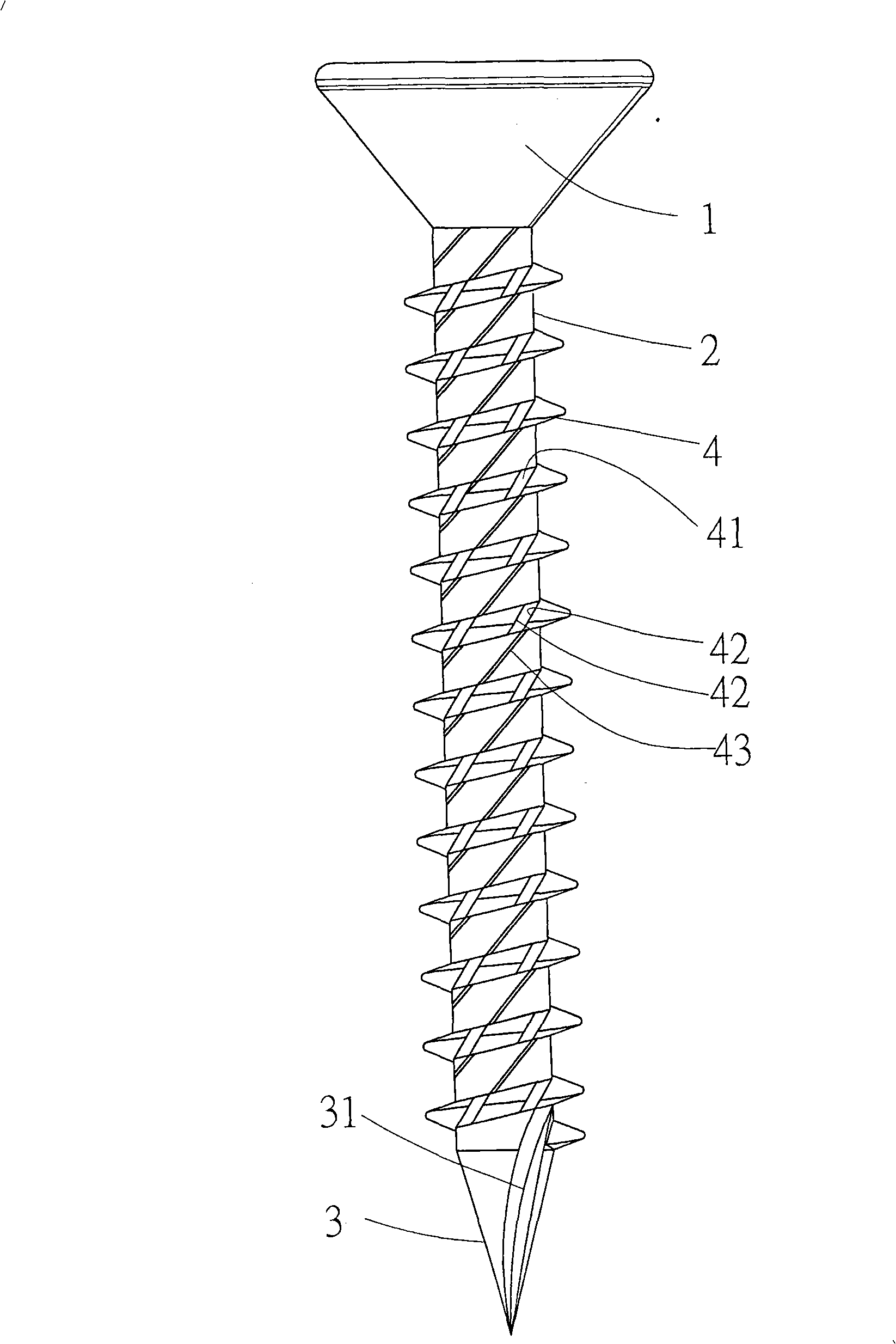
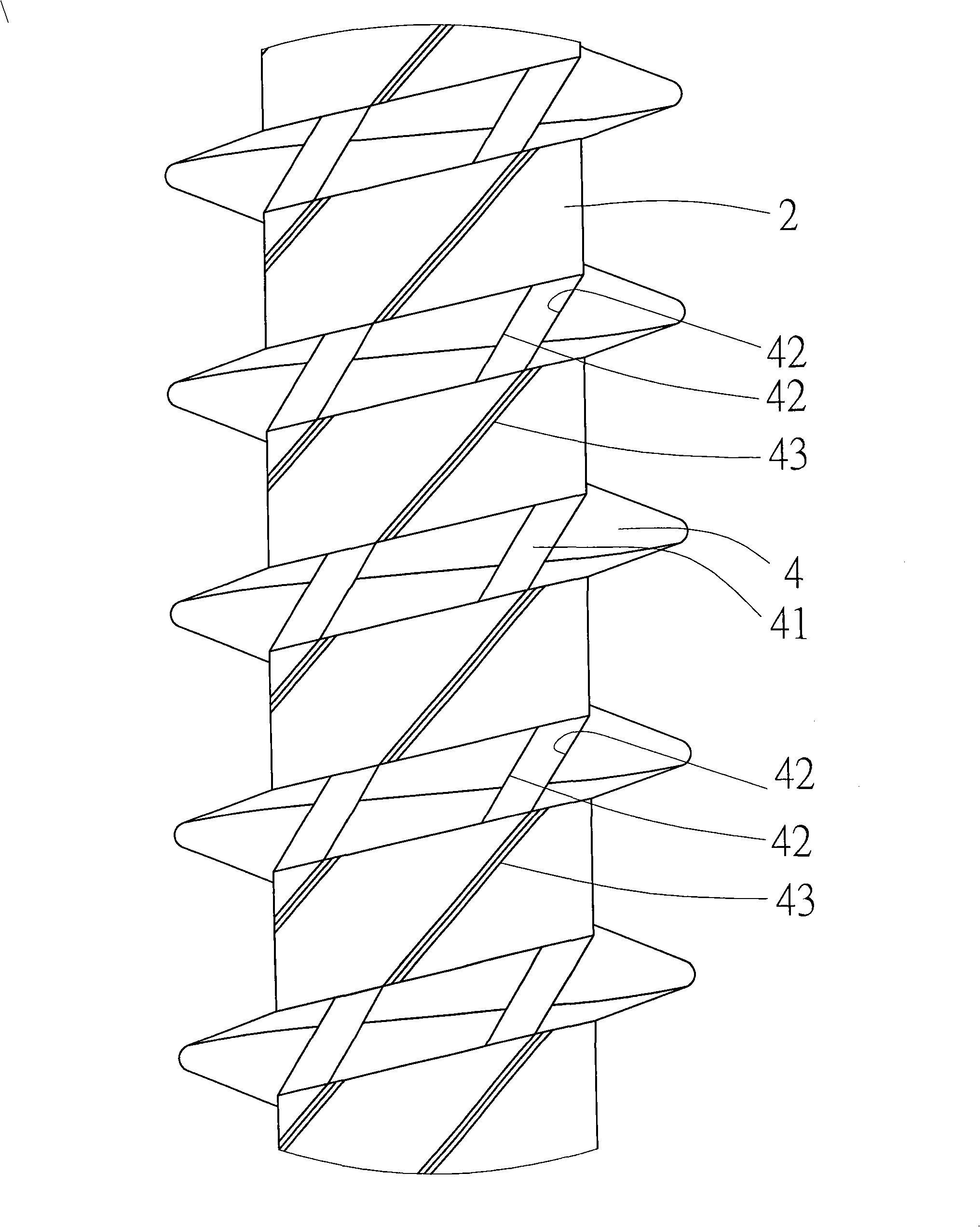
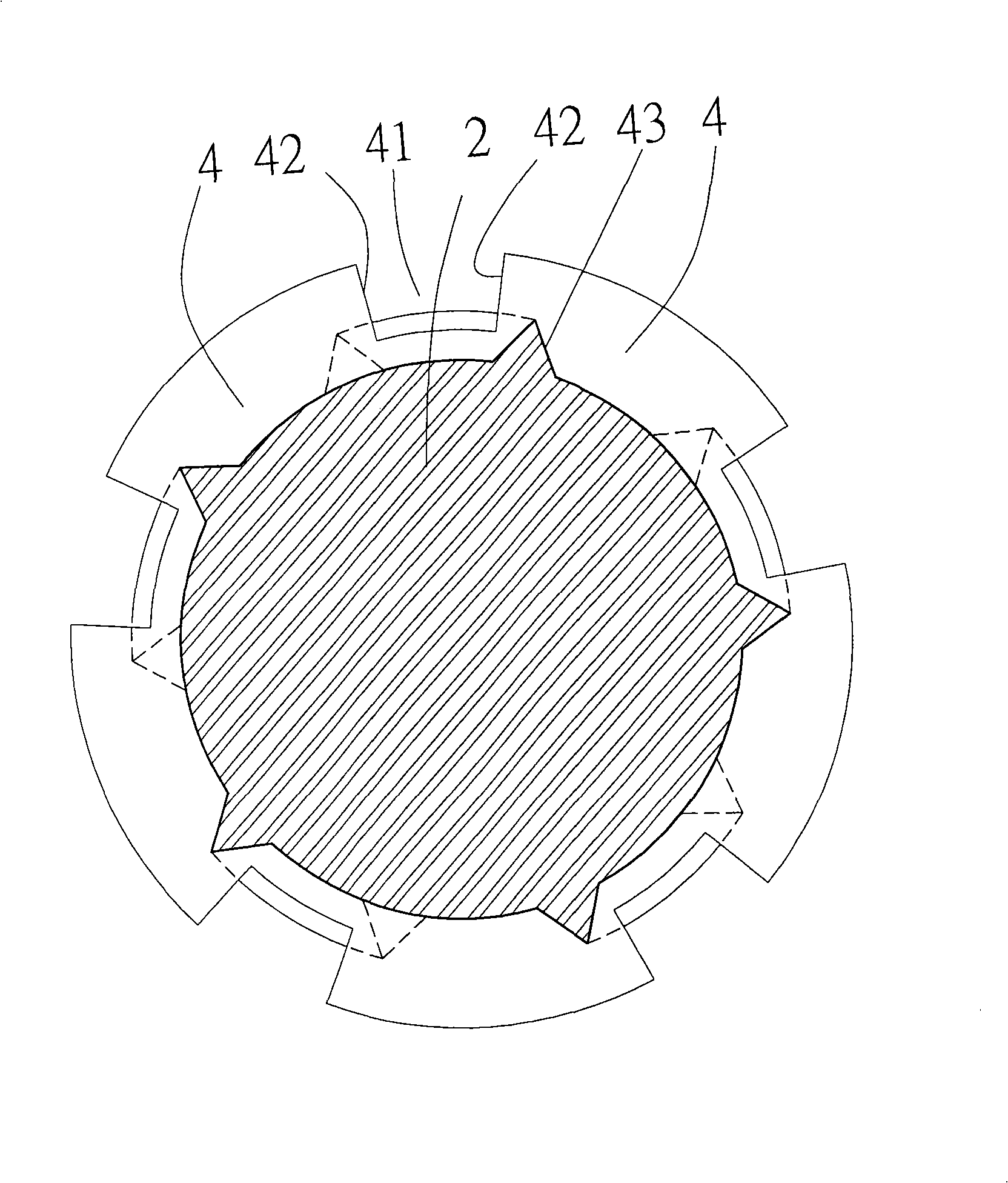
[0024] First, please also see Figure 1 to Figure 3 As shown, the screw of the present invention is divided into a nail head 1, a nail shank 2 and a nail tip 3, and the nail shank 2 spirals upwards along the nail tip 3 to the place below the nail head 1 to be provided with a thread 4, and the nail The tip 3 can also be provided with a V-shaped cutting groove 31 .

[0025] Number groove 41 is provided with number groove 41 on the number tooth pattern 4 of nail bar 2, and the two sidewalls of each groove 41 are parallel to each other, and the sidewall of each groove 41 forms auxiliary cutter 42 with tooth pattern 4 joints, and A guiding rib 43 is connected between the groove 41 of each upper thread 4 and the corresponding groove 41 of the lower thread 4 .

[0026] In addition, the recessed depth of the aforementioned groove 41 can be lower than the highest point...


PUM


Abstract

The invention discloses a screw which comprises a plurality of aslant grooves on a plurality of tooth lines of a screw rod; an auxiliary cutter is formed at the connection between the two lateral walls of each concave groove and each tooth line, while a guide rib is connectedly arranged between the concave groove of each tooth line and the concave groove of the next corresponding tooth line; during the screwing process of the screw, the guide rib can help in hole expansion, scrap pushing and keying strength enhancement, and meanwhile can utilize the guide rib in the scrap pushing process to expel scraps upwards along the concave grooves on the tooth lines smoothly, thus achieving the beneficial effects of labor-saving operation, rapid scrap expulsion and firm locking.

Description

technical field [0001] The invention relates to a screw, in particular to a screw with labor-saving operation and smooth and rapid chip removal. Background technique [0002] In terms of objects of use, screws should be regarded as the smallest, unimportant but indispensable small parts for connection, fixing, adjustment, etc. Due to different materials, functions, and positions, the required screw formats will be different. For example, the screws for connecting wood and iron are different. Because the wood is softer, the thread distance should be larger. Wood has a larger load-bearing thickness to withstand the stress of screwing; while iron is harder, the thread distance can be smaller, because iron is relatively hard, and only a small load-bearing thickness is enough to withstand screwing. Therefore, the screws manufactured by the industry are of various types and in different formats. [0003] For example, U.S. Patent No. 5,895,187, invented by the present inventor, h...

Claims


Application Information

Patent Timeline
Patent Type & Authority Applications(China)
IPC IPC(8): F16B25/04
Inventor 徐国泰
Owner 徐国泰
Learn More