Aircraft with aft split-level multi-deck fusealge and method for remoulding aircraft

An aircraft and fuselage technology, applied in the field of split-level cabin floor structure, can solve problems such as reducing passenger comfort

Active Publication Date: 2015-03-18
THE BOEING CO
View PDF7 Cites 2 Cited by
  • Summary
  • Abstract
  • Description
  • Claims
  • Application Information

AI Technical Summary

Problems solved by technology

Unfortunately, this approach often reduces passenger comfort and involves significant redesign of aircraft structural components

Method used


Image

  • Aircraft with aft split-level multi-deck fusealge and method for remoulding aircraft
  • Aircraft with aft split-level multi-deck fusealge and method for remoulding aircraft
  • Aircraft with aft split-level multi-deck fusealge and method for remoulding aircraft

Examples


Embodiment Construction

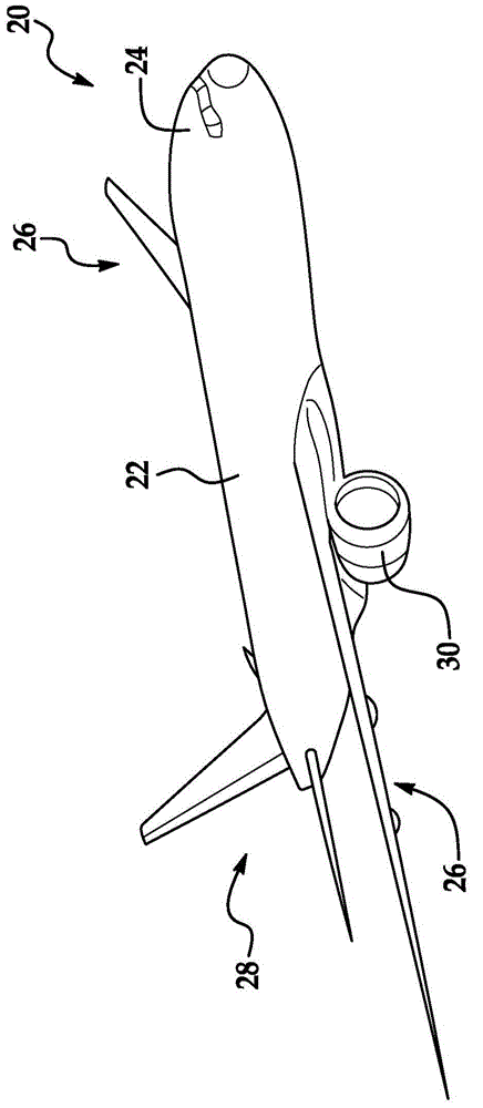
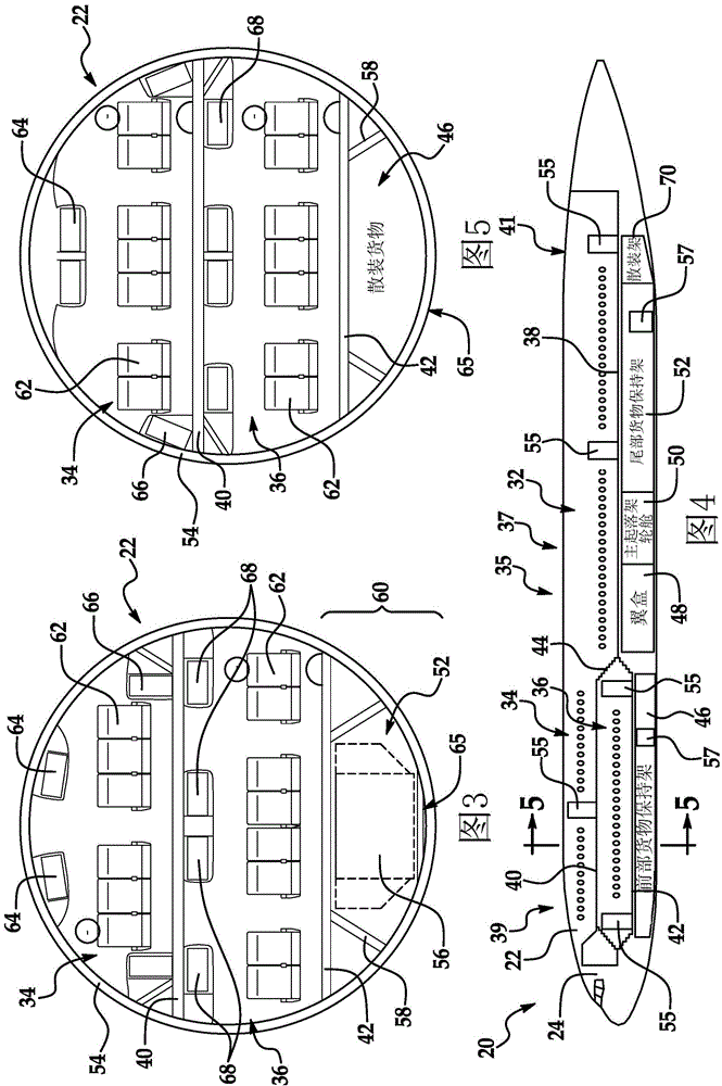
[0041] first reference Figure 1 to Figure 3 , aircraft 20 includes a generally cylindrical fuselage 22 to which wing assemblies 26 and tail assemblies 28 are attached. In the illustrated example, aircraft 20 is propelled by jet engines 30 mounted on wing assemblies 26, as figure 1Best seen. Aircraft 20 may carry any of various types of payload, including cargo and passengers. As used herein, the term "passenger" is intended to include all forms of passengers, including crew members, pilots, entourage and service personnel.

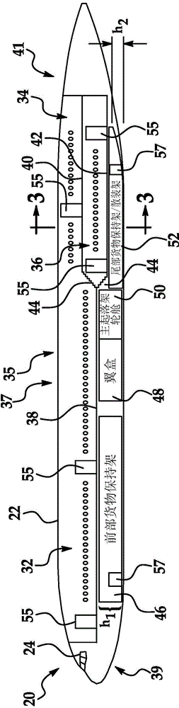
[0042] Now especially with reference to figure 2 with image 3 , the fuselage 22 broadly includes a crew cockpit 24 positioned forward and a split-level cabin layout 35 comprising: a first main-level cabin 32 positioned immediately behind the cockpit 24; and an upper Second cabin 34 and lower third cabin 36, they are positioned between main cabin 32 and tail assembly 28 ( figure 1 )between. Passenger compartments 32, 34 and 36 include passenger co...


PUM


Abstract

An aircraft capable of carrying passengers and cargo includes a fuselage (22), having a crown section (164) and a keel (106), a first passenger cabin (120), having a first floor (132), located in a forward portion the fuselage, and a first cargo deck (134), located below at least a portion of the first passenger cabin (120). A split level cabin (35) is located in an aft portion of the fuselage (22), the split level cabin (35) including an upper second cabin (124) having a second floor (156) above the level of the first floor (132), and a lower third cabin (126) beneath the upper second cabin (124) and having a third floor (158) below the level of the first floor (132). A second cargo deck (160) is located in the aft portion of the fuselage and beneath at least a portion of the lower third cabin. The crown section has a substantially constant cross-sectional shape fore-to-aft above the first passenger cabin and the split level cabin, and the keel below the second cargo deck is lowered compared to the keel below the first cargo deck. A modified aircraft having a split level aft cabin and lowered keel, and a method for modifying an aircraft in this way are disclosed.

Description

technical field [0001] The present disclosure relates generally to aircraft fuselage construction and cabin layout, and more particularly to split-level cabin floor construction. Background technique [0002] The operational efficiency of commercial and military aircraft can depend on the efficient use of the volume of space within the fuselage of the aircraft. Optimizing the use of fuselage volume allows aircraft to carry higher payloads of passengers and / or cargo. The ability to carry higher yield payloads reduces operating expenses relative to yield while reducing fuel burn per seat mile and / or ton mile and CO per seat mile and / or ton mile 2 produce. The challenge of optimizing the use of available fuselage volume is complex due to the need to provide passenger comfort and safety while accommodating associated cargo requirements. Ultimately, passenger cabin layout and design must take into account the need for ditch energy absorption in the lower region of the fuselage...

Claims


Application Information

Patent Timeline
Patent Type & Authority Applications(China)
IPC IPC(8): B64C1/18B64C1/00
CPCB64C7/00B64C2001/0027B64D11/00B64C1/00B64C2001/0045Y02T50/40
Inventor M·M·K·V·桑里提S·D·巴尔米切夫
Owner THE BOEING CO
Why Eureka
Try Eureka