Internal tooth snap ring of fluid pipe connection apparatus

A technology of connecting device and internal tooth snap ring, which is applied in the direction of mechanical equipment, couplings, etc., can solve the problems that it is difficult to embed into the pipe wall, the depth of internal teeth embedded in the pipe wall cannot be controlled, and it is stuck into the pipe groove, so as to achieve good protection. Effect

Inactive Publication Date: 2008-12-24
黎莲威
View PDF2 Cites 10 Cited by
  • Summary
  • Abstract
  • Description
  • Claims
  • Application Information

AI Technical Summary

Problems solved by technology

[0006] The invention firstly solves the problem that the front ends of the internal teeth that are squeezed to be close to parallel to the pipe wall are difficult to embed into the pipe

Method used


Image

  • Internal tooth snap ring of fluid pipe connection apparatus
  • Internal tooth snap ring of fluid pipe connection apparatus
  • Internal tooth snap ring of fluid pipe connection apparatus

Examples


Example Embodiment

[0020] Example one

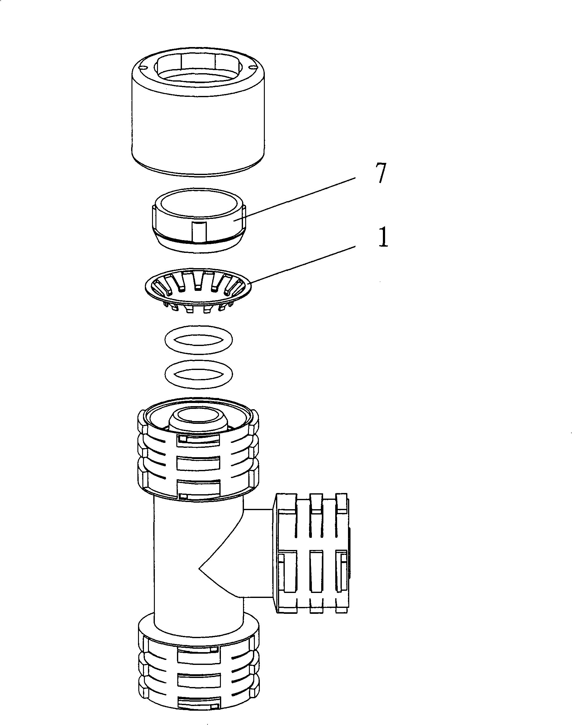
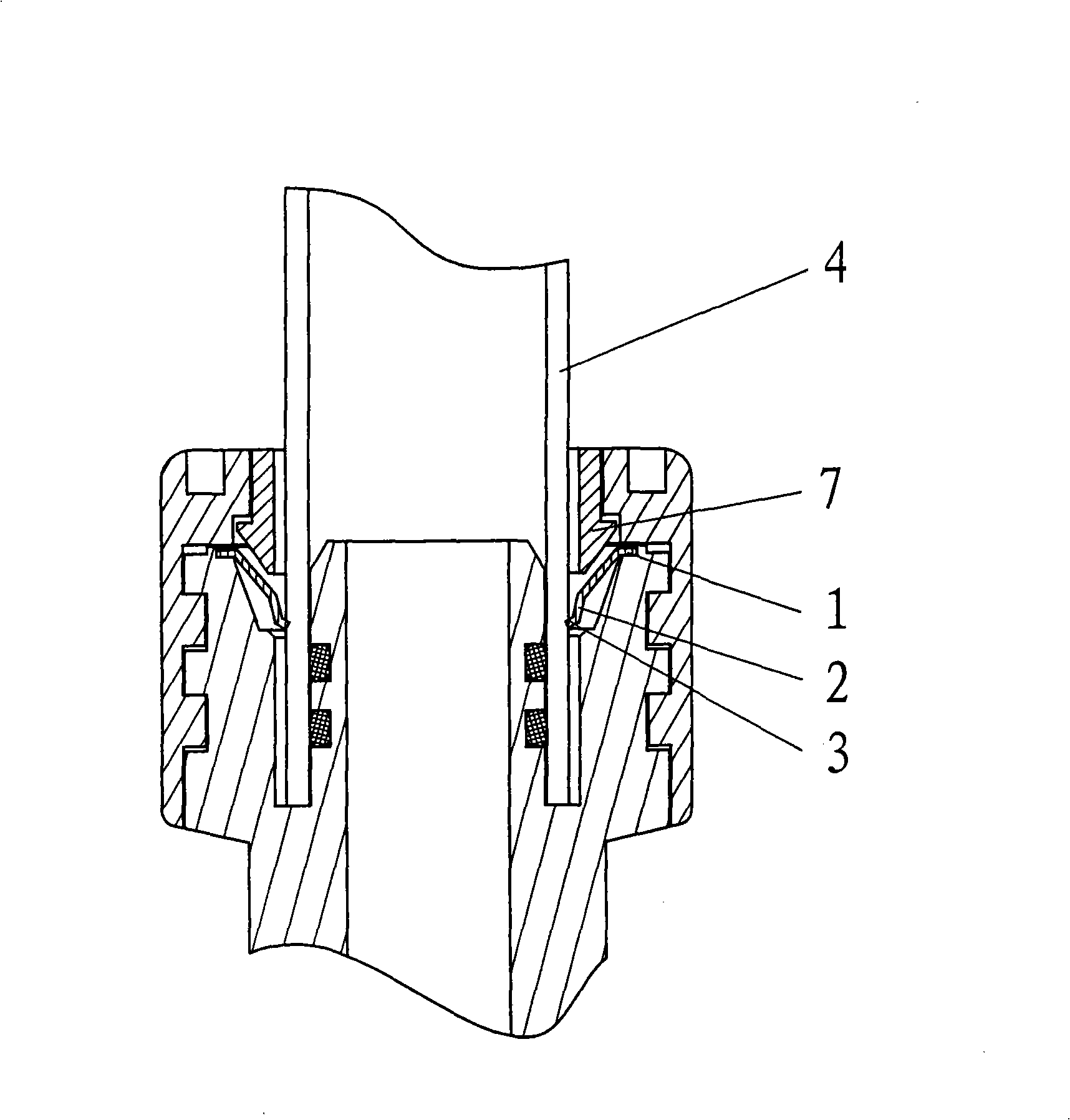
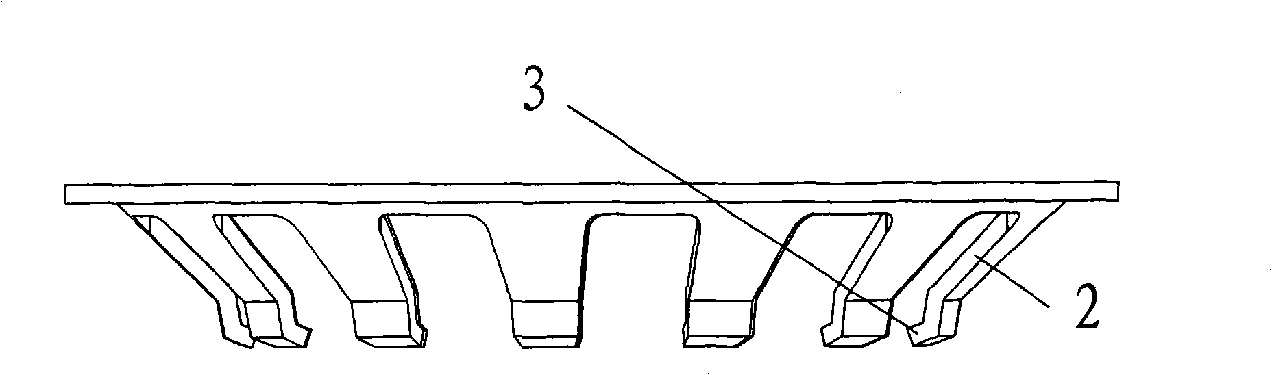
[0021] Such as figure 1 The fluid pipe connection device includes an internal tooth snap ring 1. After the fluid pipe connection is completed, such as figure 2 As shown, the front end 3 of the internal tooth is embedded in the pipe wall 4, and the internal tooth snap ring 1 is as image 3 , 5 . The front end 3 of the internal teeth is bent toward the exit direction of the pipe, and the front end 3 of the bent internal teeth is about 2 mm long. The depth of the internal teeth embedded in the pipe wall 4 depends on the length of the front end 3 of the bent internal teeth. The rear part 2 of the internal tooth protrudes in a direction close to the tube wall 4.

[0022] In the spliced ​​state, the fluid flow in the pipeline causes the pipe wall 4 to receive a force in the exit direction of the pipeline. This force is transmitted to the rear part 2 of the inner tooth through the front end 3 of the inner tooth, so that the rear part 2 of the inner tooth is compres...

Example Embodiment

[0023] Example two

[0024] Such as Figure 6 It is another internal tooth structure of the internal tooth snap ring of the present invention, and the front end 3 of the internal tooth is bent toward the exit direction of the pipe. The rear part 2 of the internal teeth in this embodiment is basically in a straight line, which makes it difficult for the push ring to push the internal teeth away when the tube is removed.


PUM


Abstract

The invention provides a snap ring for an internal tooth of a fluid tube connecting device, which aims at solving the problems that: when a pipeline is jointed, the front end of the internal tooth which is squeezed to be nearly parallel to the tube wall is difficult to be embedded into the tube wall or be clamped in the pipe chase, and the embedded depth to the tube wall can not be controlled. The snap ring comprises the internal tooth which is squeezed when the pipeline is embedded, and the tube wall for tightly clamping the front end of the internal tooth when in connection stage, and is characterized in that the front end of the internal tooth is bent to the direction to which the pipeline withdraws.

Description

technical field [0001] The invention relates to an inner-tooth snap ring used for clamping the pipe wall at a fluid pipe connection device. Background technique [0002] Chinese Patent No. 200310101202.7 (hereinafter referred to as the reference document) with the authorized announcement number CN1324258C describes a fluid pipe connection device for guiding the flow of fluids such as water or gas (the reference document is referred to as "water or steam pipe connection device"), including A pipe joint and a plug sleeve that can be fastened on the pipe joint, and the plug sleeve is sleeved outside the pipe wall after being passed through by the pipe. An internal tooth snap ring (referred to as "internal tooth lock ring 3" in the reference file) and a push tooth ring (referred to as "opening and closing ring 2" in the reference file) are installed between the pipe joint and the plug sleeve. During the connection, the pipe passes through the plug sleeve and the push tooth ring...

Claims


Application Information

Patent Timeline
IPC IPC(8): F16L37/091
CPCF16L37/0915
Inventor 黎莲威
Owner 黎莲威
Why Eureka
Try Eureka