
Drainage combined with sludge-cleaning vehicle sludge-water separating system

A mud-water separation and sewage cleaning vehicle technology, which is applied in dehydration/drying/concentrated sludge treatment, filtration separation, separation methods, etc., can solve the problems of complex structure, difficult and high cost of manufacturing, and difficulty in achieving long-term reliable work. Achieve the effect of simple manufacturing process

Inactive Publication Date: 2008-12-31
WUHAN UNIV OF TECH +1
View PDF0 Cites 16 Cited by
  • Summary
  • Abstract
  • Description
  • Claims
  • Application Information

AI Technical Summary

Problems solved by technology

[0009]3. The sewage circulation system requires a relatively long settling time because it has to go through several stages of filtration; the structure of the other stages of filter chambers will also be more complicated and difficult to manufacture The cost and cost are very high and it is difficult to achieve long-term reliable work; although it has undergone several stages of physical filtration, the filtered water still contains many particles and chemical substances, which will cause the high-pressure water pump with high water quality requirements to be corroded to a certain extent. shortened its life

Method used


Image

  • Drainage combined with sludge-cleaning vehicle sludge-water separating system
  • Drainage combined with sludge-cleaning vehicle sludge-water separating system
  • Drainage combined with sludge-cleaning vehicle sludge-water separating system

Examples


Embodiment Construction

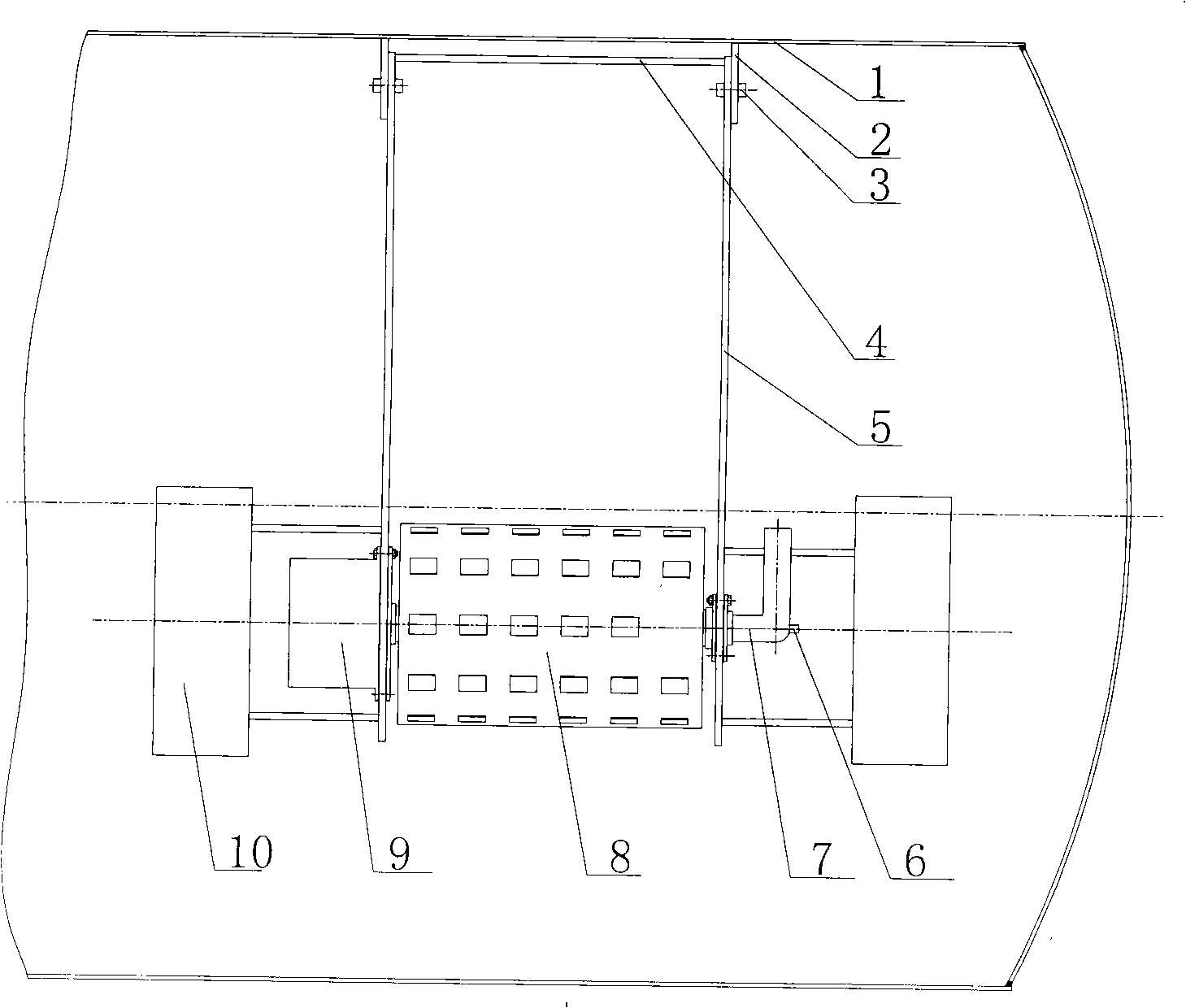
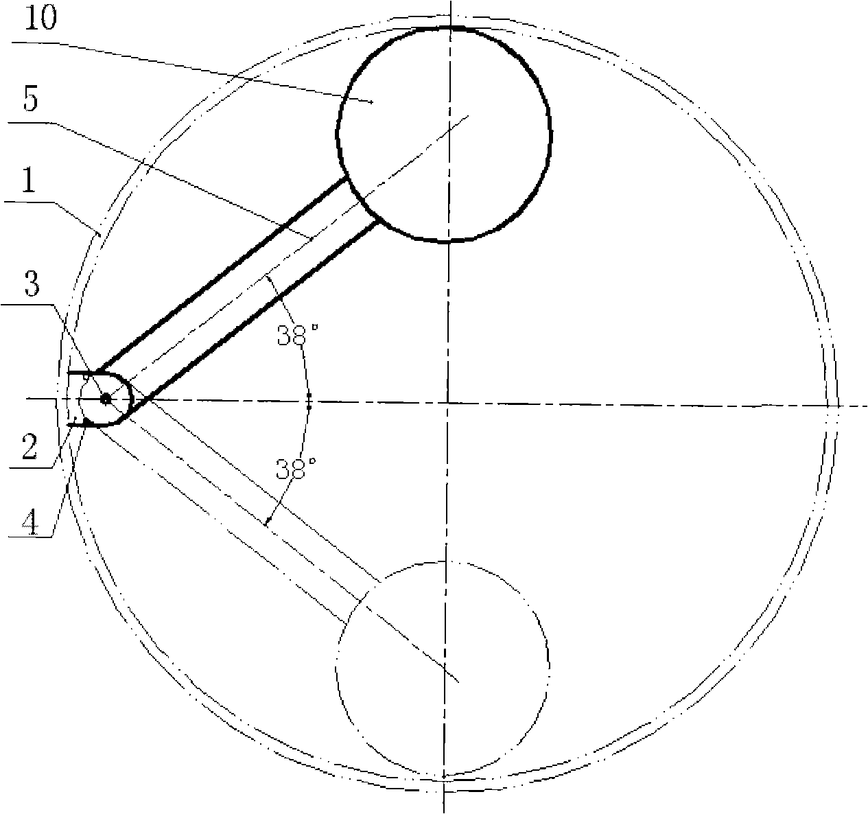
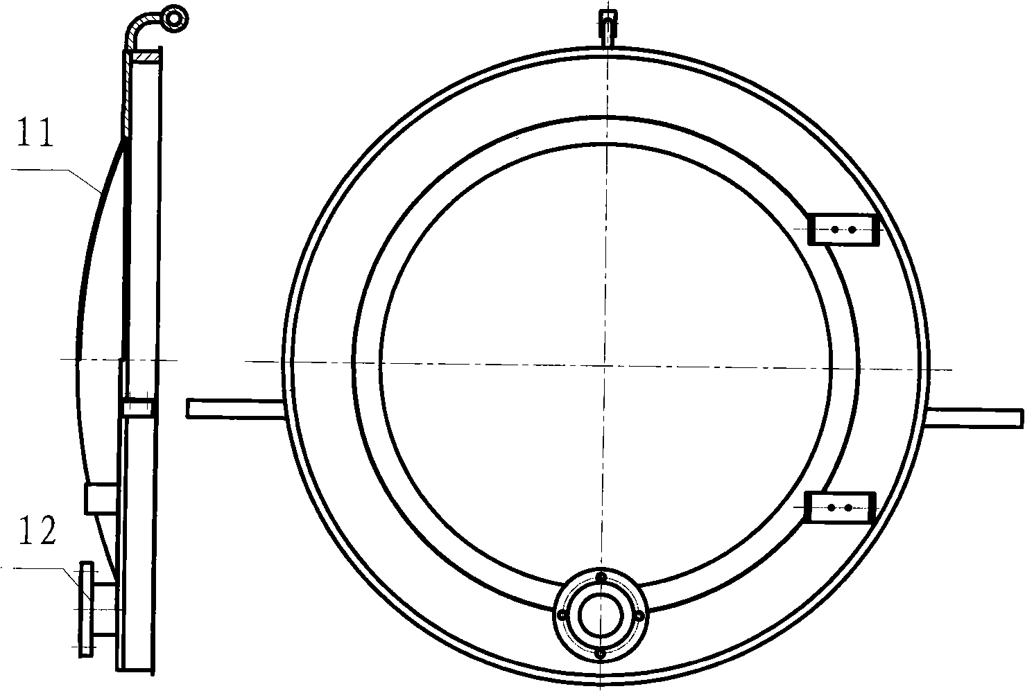
[0024] The structure of the sludge-water separation system of the sewer united cleaning vehicle of the present invention is as follows: Figure 4 shown. The system is mainly composed of a rotary filter cartridge 8, a bracket 5, a buoy 10, a sewage pump, a hydraulic motor 13, a backwash pipeline 6, a mud discharge valve 12, connecting pipes and various valves. The buoy 10 is coaxially installed at both ends of the rotating filter cartridge 8, and the journals at both ends of the rotating filter cartridge are respectively supported by deep groove ball bearing 14 and deep groove ball bearing 2 18 on the lower part of the bracket 5, and the upper part of the bracket 5 is passed through the hinge pin The shaft 3 is installed on the installation support 2 in the sludge tank 1. Under the buoyancy of the buoyancy drum 10, all the devices installed on the lower part of the support 5 are always suspended in the liquid, and the central axis of the rotating filter cartridge is always just ...


PUM


Abstract

A sludge-water separation system for a combined sewer sludge-cleaning vehicle comprises a rotary filter cylinder (8), a bracket (5), a buoy (10), a sewage pump, a hydraulic motor (13), a high-pressure backwashing water pipe (6), a sludge discharge valve (12), as well as connecting pipes and valves; wherein, the rotary filter cylinder and the sewage pump adopt hydraulic drive. During operation, the slurry sucked into a sludge tank is filtered through the sieve of the rotary filter cylinder, then pumped out of the tank body through the sewage pump, and finally discharged into the sewer. Therefore, the sludge tank can continue suck sludge and sewage. The hydraulic motor drives the rotary filter cylinder to endlessly rotate to prevent the sieve of the filter cylinder being jammed by the dirt in the sludge tank. The high-pressure backwashing water pipe effectively ensures the smooth screening of the sieve and can thoroughly wash the rotary filter cylinder after the completion of the sludge-cleaning operation so as to reduce the corrosion of the system caused by the slurry and make sure the operation can go on smoothly. The remaining viscous sludge in the tank body is discharged out of the vehicle through a sludge discharge valve, then collected or naturally dried and finally carried to refuse sites.

Description

technical field [0001] The invention relates to a vehicle-mounted mud-water separation system, in particular to the mud-water separation system for a sewer united sewage cleaning vehicle. Background technique [0002] With the rapid development of modern urban construction, the length of urban sewers is also increasing rapidly, and the dredging work of sewers is becoming more and more arduous. Because the manual dredging of urban sewers is slow and very difficult, and sometimes even has the risk of casualties, the mechanization of urban sewer dredging will become inevitable. As one of the sanitation vehicles, the sewer cleaning vehicle has the functions of flushing the sewer, suctioning sludge, realizing timely dredging of the sewer, purifying the air, and beautifying the environment. It is an important equipment for urban environmental protection and construction. It is generally believed that the sewer cleaning vehicle refers to the function of flushing the sewer or sucti...

Claims


Application Information

Patent Timeline
Patent Type & Authority Applications(China)
IPC IPC(8): C02F11/12E03C1/30B01D33/067B01D33/50
Inventor 过学迅吴保玉杨涛徐达乔维高田豪石又新刘江河
Owner WUHAN UNIV OF TECH
Learn More