Space fragment and micrometeoroid impact resistant protection mechanism capable of inflating and expanding on rails

An inflatable deployment and protection mechanism technology, which is applied in the directions of aerospace vehicle anti-meteorite devices, aerospace safety/emergency devices, etc., can solve the problems of difficulty in achieving the folding efficiency of protective screens, difficulty in building multi-layer protection, and low deployment reliability. High deployment efficiency, good deployment reliability and good protection effect

Inactive Publication Date: 2010-08-11
HARBIN INST OF TECH
View PDF0 Cites 0 Cited by
  • Summary
  • Abstract
  • Description
  • Claims
  • Application Information

AI Technical Summary

Problems solved by technology

[0003] The purpose of the present invention is to solve the problems of high cost, difficulty, or even difficulty in realizing large-sized protective screens that are space-assembled by one-shot or multiple launches, and the low folding efficiency and low deployment reliability of mechanically unfolded protective screens. , the small volume after deployment, and the difficulty of constructing more than three or more layers of multi-layer protection, and then provide a protection mechanism that can be inflated and deployed in orbit to resist space debris and micrometeoroid impacts

Method used


Image

  • Space fragment and micrometeoroid impact resistant protection mechanism capable of inflating and expanding on rails
  • Space fragment and micrometeoroid impact resistant protection mechanism capable of inflating and expanding on rails
  • Space fragment and micrometeoroid impact resistant protection mechanism capable of inflating and expanding on rails

Examples


specific Embodiment approach 1

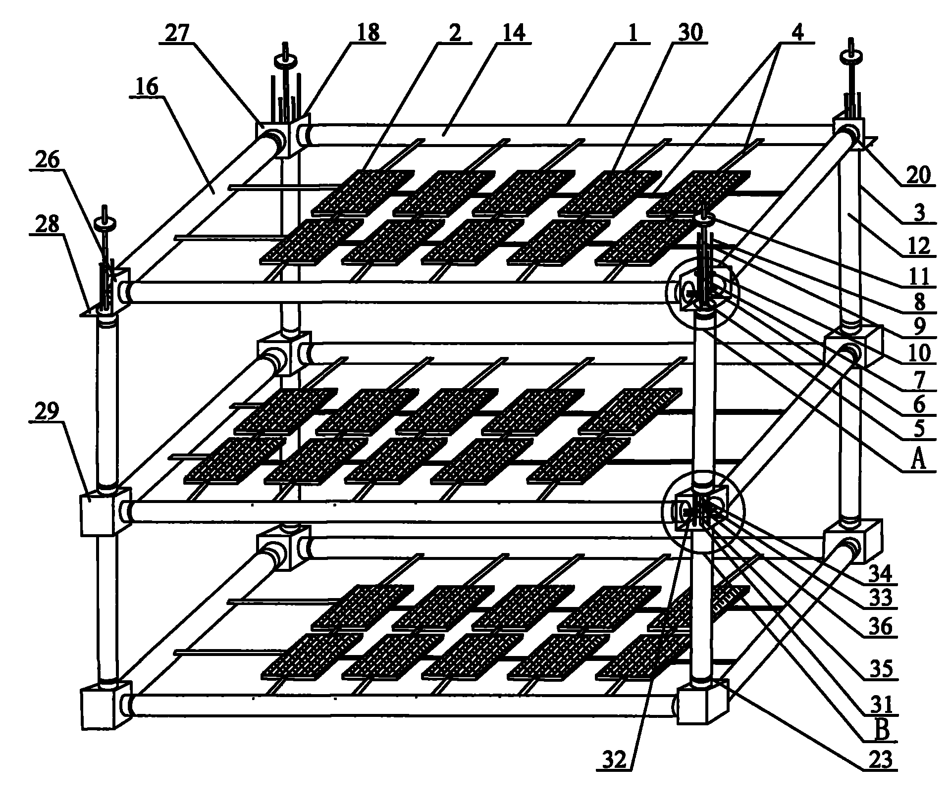
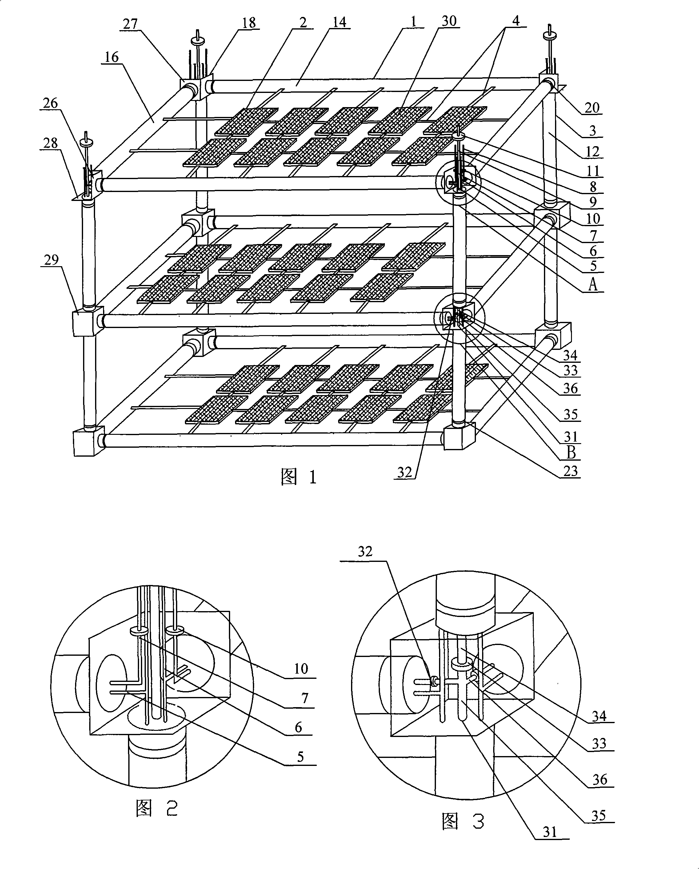
[0007] Specific Embodiment 1: This embodiment is described with reference to FIGS. 1 to 4 and FIGS. 9 to 11 . An inflatable deployment support riser assembly 3, a plurality of ties 4, at least two horizontal wires 5, four pairs of vertical parallel wires 6, two first inflatable tubes 7, two second inflatable tubes 8, four vertical Straight inflatable pipe 9, four horizontal inflatable control valves 10 and four control valves 11; the at least two layers of stiffened inflatable unfolded planar frames 1 are facing up and down and arranged in parallel, and the adjacent two layers of stiffened inflatable unfolded planar frames The four corner ends of 1 are connected by four inflatable deployment support riser assemblies 3 to form an airtight inflatable deployment support frame, and a protective screen 2 is arranged in each layer of rigid inflatable deployment plane frame 1, and each layer Each protective screen 2 is connected with the corresponding stiffened inflatable unfolded pl...

specific Embodiment approach 2

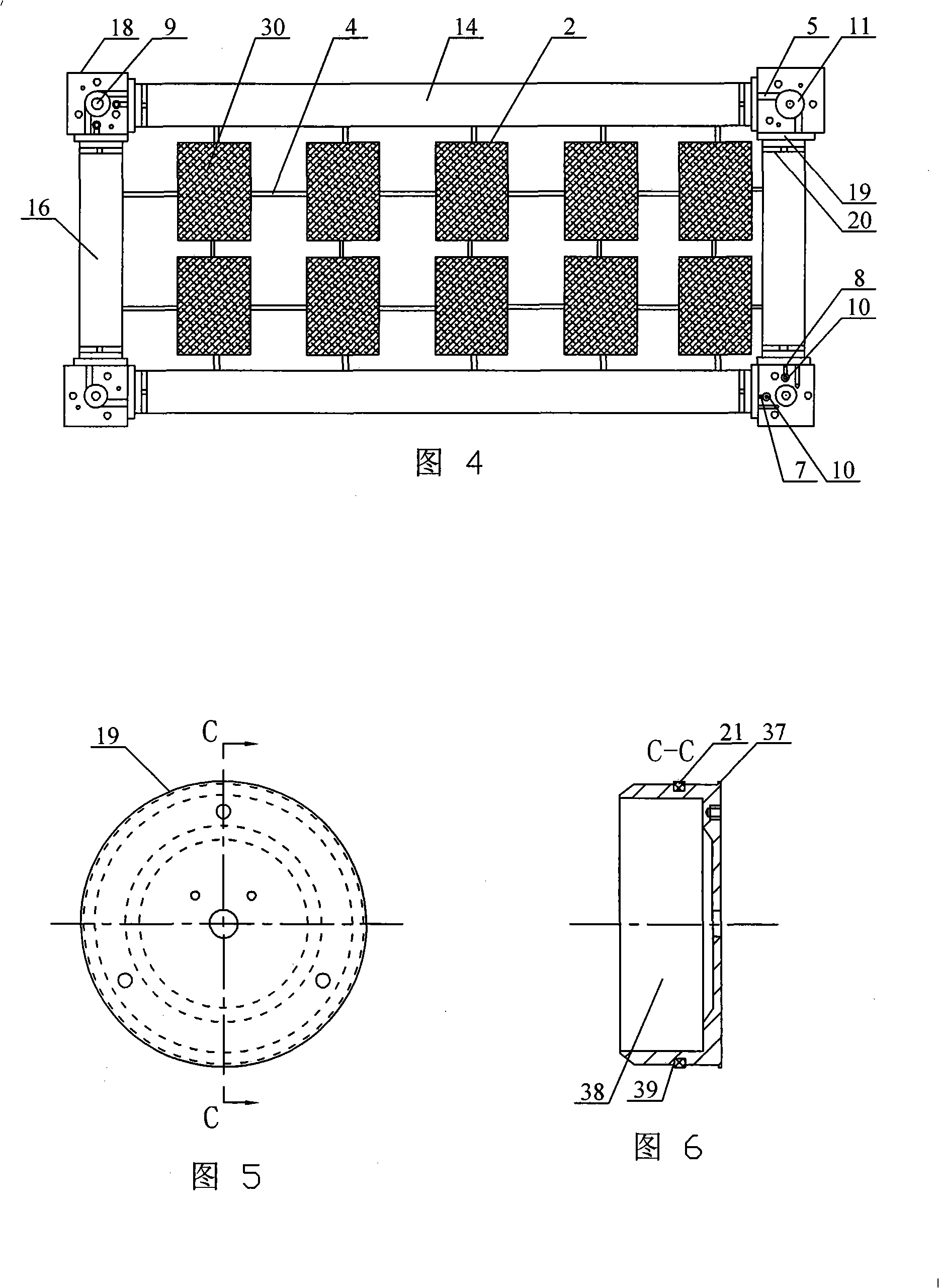
[0008] Specific Embodiment 2: This embodiment will be described with reference to FIGS. 1 to 4 , 5 and 6. Each layer of rigid inflatable and unfoldable planar frame 1 in this embodiment consists of two rigid inflatable and expandable long support tubes 14, two One stiffenable inflatable expandable short support tube 16, four connectors 18, eight end caps 19, eight clamps 20 and eight sealing rubber rings 21; the two rigidizable inflatable expandable long support tubes 14 and two stiffenable inflatable and expandable short support tubes 16 are set opposite to each other to form a rectangular frame, each corner of the rectangular frame is respectively provided with a connecting piece 18, each of the rigidizable inflatable expandable long support tubes An end cover 19 is installed respectively in the two ends of 14 and in the two ends of each stiffenable inflatable deployment short support tube 16, and the end cover 19 is connected with the stiffenable inflatable through the seali...

specific Embodiment approach 3

[0009] Specific Embodiment Three: This embodiment is described with reference to Figs. 1 to 4, Fig. 7 and Fig. 8. Each inflatable deployment support riser assembly 3 in this embodiment consists of a rigidizable inflatable deployment support riser 12 and two connection plates. 22. Two throat hoops 23 and two sealing rubber rings 24; each of the two ends of each stiffened inflatable support standpipe 12 is equipped with a connecting plate 22, and the connecting plate 22 is installed on its outer wall The sealing rubber ring 24 is airtightly connected with the inner wall of the stiffening inflatable support standpipe 12, and a hose clamp 23 is respectively installed on the outer wall of each stiffenable inflatable spread support standpipe 12 two ends, and each can be rigidified inflatable expand support standpipe 12. The two ends of the support standpipe 12 are fixedly connected to the connection plate 22 through the throat clamp 23 respectively, and the two ends of each rigidizab...


PUM


Abstract

A defense mechanism which can be charged and unfolded on track and is capable of resisting the impact from space debris and micrometeoroid relates to a defense mechanism for resisting the impact from space debris and micrometeoroid, aiming at solving the problems of high cost and big difficulty in large size defense screens assembled in space for one or more launches and the problems of low folding efficiency, low reliability and small size after being unfolded on mechanically unfolded defense screens. Two adjacent layers of plane frames which can be hardened and can be unfolded by charging are connected through a support upright pipe assembly which can be unfolded by charging, and defense screens are arranged in the plane frames which can be hardened and can be unfolded by charging and are connected with the plane frames which can be hardened and can be unfolded by charging; horizontal leads and air inlet pipes are arranged inside the plane frames which can be hardened and can be unfolded by charging; vertical parallel leads and charging pipes are arranged inside the support upright pipe assembly which can be unfolded by charging; the horizontal leads are connected with the vertical parallel leads; the first charging pipe and the second charging pipe are communicated with short and long support pipes which can be hardened and can be unfolded by charging; the vertical chargingpipes are communicated with the support upright pipes which can be hardened and can be unfolded by charging. The defense mechanism is good in defending effect, high in reliability, light in weight, high in folding efficiency and low in cost.

Description

technical field [0001] The invention relates to a protection mechanism against space debris and micrometeoroid impact. Background technique [0002] There are a large number of high-speed moving (speed ≥ 8km / s) micrometeoroids and space debris in the orbital space of spacecraft such as satellites. The impact of these micrometeoroids and space debris will cause damage, destruction or even failure of the aircraft. It poses a serious threat to the safety of astronauts. For space debris larger than 1 cm, early warning can be given through on-orbit debris monitors, and active protective measures such as avoidance can be taken; for space debris smaller than 1 cm, only passive protective measures can be used. At present, the protection schemes of spacecraft mainly include two kinds of protective screen mechanisms: fixed type and mechanical type. Spacecraft often require a larger-sized protective area and a larger-sized protective screen. Due to the limitation of launch volume an...

Claims


Application Information

Patent Timeline
Patent Type & Authority Patents(China)
IPC IPC(8): B64G1/52B64G1/56
Inventor 苗常青王友善曹昱谭惠丰杜星文
Owner HARBIN INST OF TECH
Why Eureka
Try Eureka