
Multi-layer cavity type inflating expansion protection mechanism

A technology of inflatable deployment and protective mechanism, which is applied in the direction of aerospace vehicle anti-meteorite devices, aerospace safety/emergency devices, etc. It can solve the problems of low folding efficiency, low deployment reliability and small size of space debris impact damage, and achieve inflatable deployment. The process is stable, the protection effect is good, and the emission volume is small

Inactive Publication Date: 2010-08-18
HARBIN INST OF TECH
View PDF0 Cites 0 Cited by
  • Summary
  • Abstract
  • Description
  • Claims
  • Application Information

AI Technical Summary

Problems solved by technology

[0003] The purpose of the present invention is to solve the problems that a single-layer protective screen is difficult to effectively protect against the impact damage of space debris and the mechanically deployed protective mechanism has low folding efficiency, low deployment reliability, and small volume after deployment, and further provides a multi-layer protective screen. Cavity inflatable deployment protection mechanism

Method used


Image

  • Multi-layer cavity type inflating expansion protection mechanism
  • Multi-layer cavity type inflating expansion protection mechanism
  • Multi-layer cavity type inflating expansion protection mechanism

Examples


specific Embodiment approach 1

[0008] Specific Embodiment 1: This embodiment will be described with reference to FIGS. 1 to 7 and 19. This embodiment includes an inflatable support frame to be stiffened 1, at least two layers of protective screens, at least three inflatable support tubes to be stiffened 2, and at least three supports Tube inflation pipe 3, a main inflation pipe 4, at least one outlet pipe 5, at least three second electromagnetic inflation valves 6, at least six throat clamps 7 and at least six second end caps 8; the adjacent two The peripheral parts of the layers of protective screens are bonded together to form at least two layers of cavity-type inflatable expansion protection screens to be stiffened, and the at least two layers of cavity-type inflatable expansion protection screens to be stiffened are arranged on the inflatable support frame to be stiffened 1 and connected with the inflatable support frame 1 to be stiffened, one end of the main inflation tube 4 is installed in at least two...

specific Embodiment approach 2

[0010] Specific implementation mode two: the number of layers of the cavity-type inflatable protective screen to be rigidified in this embodiment is 2-20 layers, and the thickness of each layer of the cavity-type inflatable protective screen to be rigidified is 0.1cm- 5cm, and the diameter of the cavity-type inflatable deployment protective screen to be rigidified is 0.5m-10m. Such setting can resist the impact damage of space debris. Other components and connections are the same as those in the first embodiment.

specific Embodiment approach 3

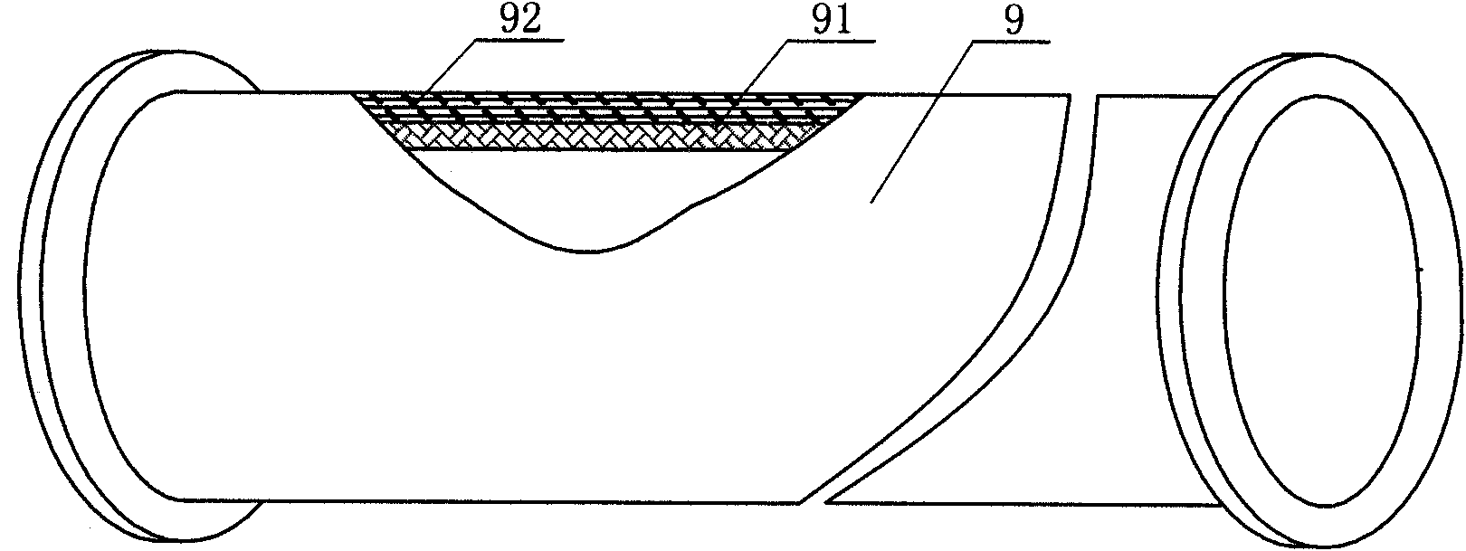
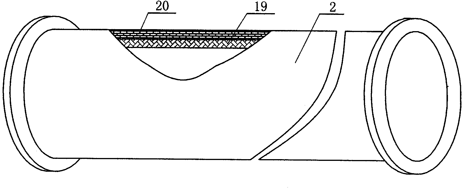
[0011] Specific Embodiment Three: This embodiment is described in conjunction with Fig. 1, Fig. 4, Fig. 9 and Fig. 10. The cavity-type inflatable deployment protective screen to be rigidized in this embodiment is a flexible cavity-type inflatable deployment protection screen to be rigidified 16. Each layer of the flexible cavity-type inflatable inflatable protective screen 16 to be stiffened includes a gas isolation layer 17 and a solidified layer 18 that are stacked and fixed together; each tube of the inflatable support tube 2 to be stiffened The wall includes a gas barrier layer 19 and a thermosetting layer 20 affixed together from the inside to the outside, and the tube wall of each inflatable tube 9 to be rigidified includes a barrier layer 91 and a thermosetting layer affixed together from the inside to the outside. Layer 92, the material for making the cured layer 18, the thermosetting layer 20 and the thermosetting layer 92 is a thermosetting resin prepreg fabric, and t...


PUM


Abstract

A multi-layer cavity-type aeration for expansion protection mechanism relates to an aeration for expansion protection mechanism, which aims at solving the problems that a monolayer protection screen can not effectively avoid the damage caused by the collision from the space chippy fraction, and a mechanism-typed expansion protection mechanism has low folding efficiency, low expansion reliability and a small volume after expansion. Parts of the periphery of the adjacent two protection screens cling together to form a cavity-type aeration for expansion protection screen to be rigidified, which is connected with an aeration supporting frame to be rigidified; a main inflation pipe is arranged in the cavity-type aeration for expansion protection screen to be rigidified and communicated with anair-discharging pipe; the lower end of the aeration supporting frame to be rigidified is provided with an aeration supporting pipe to be rigidified, which is communicated with the inflation pipe of asupporting pipe; two ends of an aeration bent pipe are communicated with an aeration pipe to be rigidified and the aeration supporting pipe to be rigidified. The invention can avoid the damage causedby the collision from the space chippy fraction, and has the advantages of high folding efficiency, high expansion reliability and a large volume after expansion.

Description

technical field [0001] The invention relates to an inflatable deployment protection mechanism, in particular to a protection mechanism for astronauts and spacecraft against impact damage from space debris and micrometeoroids. Background technique [0002] All kinds of spacecraft in low earth orbit and astronauts going out for spacewalks are vulnerable to ultra-high-speed impacts from micrometeoroids and space debris. These impacts damage the key systems of the spacecraft flight, leading to catastrophic failure of the spacecraft, threatening the safety of the astronauts and the normal operation of the spacecraft. Therefore, it is necessary to use protective mechanisms to protect the key parts of the spacecraft and the astronauts. very necessary. It is difficult for a single-layer protective screen to effectively protect against space debris impact damage; mechanically deployed protective mechanisms have disadvantages such as low folding efficiency, large launch volume, low d...

Claims


Application Information

Patent Timeline
Patent Type & Authority Patents(China)
IPC IPC(8): B64G1/52B64G1/56
Inventor 苗常青曹昱王友善谭惠丰杜星文
Owner HARBIN INST OF TECH
Learn More