Active interference removing apparatus for buried pipeline

A buried pipeline and anti-interference technology, which is applied in the direction of measuring devices, instruments, and measuring electrical variables, etc., can solve the problems that the cathodic protection device cannot completely eliminate AC interference, cannot eliminate AC interference, and the mismatch between control time and interference time

A buried pipeline and anti-interference technology, which is applied in the direction of measuring devices, instruments, and measuring electrical variables, etc., can solve the problems that the cathodic protection device cannot completely eliminate AC interference, cannot eliminate AC interference, and the mismatch between control time and interference time

CN101343744AActive Publication Date: 2009-01-14CHINA UNIV OF PETROLEUM (BEIJING) +2

Image

  • Active interference removing apparatus for buried pipeline
  • Active interference removing apparatus for buried pipeline
  • Active interference removing apparatus for buried pipeline

Examples


no. 1 example

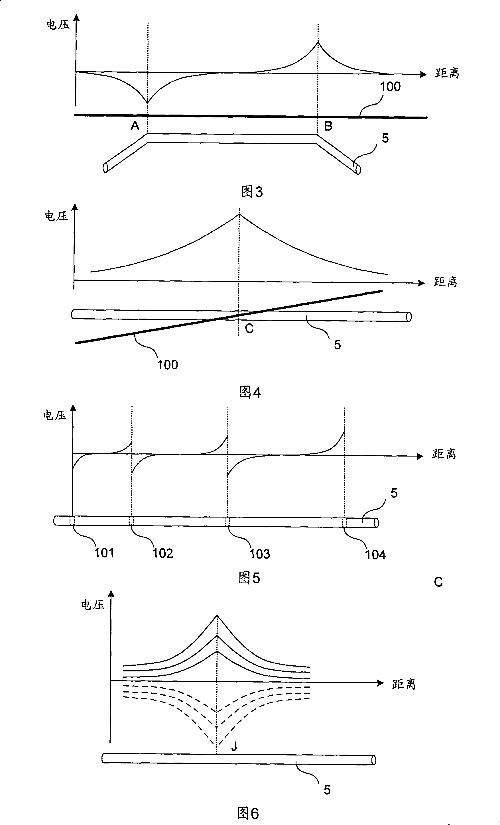
[0041] Figure 3 is a schematic diagram of the interference voltage generated on the pipeline at a certain time along the pipeline when the high-voltage transmission line and the buried pipeline are distributed in parallel, and Figure 4 is the interference voltage generated on the pipeline at a certain time when the high-voltage transmission line and the buried pipeline are distributed at a certain time Schematic diagram of distribution along the pipeline. In view of the impact of high-voltage transmission lines on buried pipelines, the inventors summarized the characteristics and laws as follows: when the high-voltage transmission line is parallel to a certain section of buried pipeline, the pipe ground potential at the end of the buried pipeline parallel to the high-voltage transmission line is the largest , The ground potential of the pipe away from the terminal gradually attenuates along the buried pipeline, as shown in Figure 3. Specifically, the section AB of the buried pipel...

no. 2 example

[0045] Figure 5 is a schematic diagram showing the distribution of interference voltage along the pipeline at a certain moment when the geomagnetic field changes caused by space weather. In view of the influence of the geomagnetic field changes on buried pipelines, the inventors summarized the characteristics and rules as follows: when long-distance oil pipelines are equipped with insulating flanges, the largest changes in the pipe ground potential caused by geomagnetic field disturbances are at the insulating flanges. On both sides, as shown in Figure 5. Specifically, at the insulating flange 101, the insulating flange 102, the insulating flange 103 and the insulating flange 104, it can be seen that the pipe ground potential of the buried pipeline caused by the change of the earth magnetic field is close to each insulating flange 101~ The two sides of the insulating flange 104 are the largest, and the ground potential of the pipe away from the insulating flange 101 to the insulat...


PUM


Abstract

The invention relates to a buried pipeline active disturbance removing device. The buried pipeline active disturbance removing device comprises a direct current power supply unit, a pipe-to-soil potential sensor, a given potentiometer, a voltage control unit and a power output unit, wherein the voltage control unit is used to generate the pulse width modulation (PWM) signal, and the power output unit is used to control the output of the internal invertor according to the pulse width modulation signal, and to output disturbance removing voltage which is performed with filtering treatment and which is equal to the pipe disturbance degree and is reverse to the direction to the auxiliary ground bed and the buried pipeline. Through adopting the tracking type PWM control method, the output of the buried pipeline active disturbance removing device of the invention can track the reference signal change of the directive voltage processing module in time, the buried pipeline active disturbance removing device has the advantages that the output sensitivity is high, the reaction speed is rapid, and the dynamic performance is good, and in particular the buried pipeline active disturbance removing device can be suitable for the eliminating of the disturbance caused by the high voltage transmission line and the space weather change.

Description

Technical field [0001] The invention relates to the field of electrochemical corrosion of buried metal pipelines, in particular to an active interference suppression device for buried pipelines. Background technique [0002] The continuous economic growth has increased the demand for energy, and the construction of power transmission lines and oil pipelines is developing rapidly. Affected by factors such as population density, land resource conditions, and the power industry and the petrochemical industry's similarity in the principle of selection of transmission paths, high-voltage transmission lines and buried pipelines are often installed in parallel or across long distances. When high-voltage transmission lines and buried pipelines are parallel or crossed, due to the influence of the alternating electromagnetic field generated by the high-voltage transmission lines, alternating voltage and current will be induced on the metal buried pipeline. [0003] Even in areas with no hu...

Claims


Application Information

Patent Timeline
14 Jan 2009
Publication
CN101343744A
IPC
C23F13/00; G01R19/165
Inventors
梁志珊