Aeration type curve ladder energy dissipater in flood discharge hole

A technology for flood discharge tunnels and energy dissipators, applied in water conservancy projects, sea area projects, coastline protection, etc., can solve the problems of difficult adjustment of flow patterns, reduce engineering investment, reduce engineering volume, etc., and achieve convenient and simple body design and construction , Reduction of engineering investment, and the effect of reducing the outlet velocity

Inactive Publication Date: 2010-06-02
SICHUAN UNIV
View PDF4 Cites 6 Cited by
  • Summary
  • Abstract
  • Description
  • Claims
  • Application Information

AI Technical Summary

Problems solved by technology

[0004] The purpose of the present invention is to overcome the deficiencies of the prior art, and provide an aeration-type curved ladder energy dissipator in the flood discharge tunnel to solve the problem of the connection between two parallel flood discharge tunnels or pressurized tunnels and downstream flood discharge tunnels with different heights. The flow rate of the flood tunnel is high, the flow state is difficult to adjust, it is easy to cause problems such as cavitation, cavitation, and low energy dissipation rate, and it reduces the engineering quantity and investment

Method used


Image

  • Aeration type curve ladder energy dissipater in flood discharge hole
  • Aeration type curve ladder energy dissipater in flood discharge hole
  • Aeration type curve ladder energy dissipater in flood discharge hole

Examples


Embodiment 1

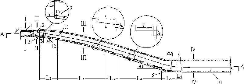
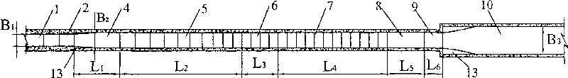
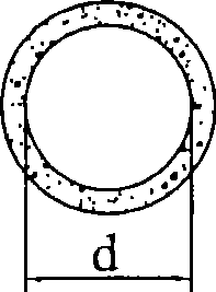
[0032] In this embodiment, the aeration-type curved ladder energy dissipator in the spillway tunnel is used for the curved connection between the upstream pressurized tunnel (empty tunnel) 1 and the downstream spillway tunnel 10 . The pressurized tunnel (vent) 1 is parallel to the downstream spillway 10, and the elevation difference between them is about 28m; the diameter d of the pressurized tunnel (vent) 1 is 3.5m, and the maximum flow Q=190m 3 / s, maximum single width flow q=54m 3 / s.m, pressure slope 2 is set at the exit, and the section gradually changes from circular to rectangular (see image 3 , Figure 4 ), the width B of the rectangular section 1 =2.5m, height H 1 =2.25m; the section of the curve connecting the cave is as follows Figure 5 shown, its width B 2 = 3.5m, the height H of the straight wall of the side wall 2 =5.0m, the maximum flow velocity at its inlet V=30m / s; the section of the downstream spillway is as follows Figure 6 shown, its width B 3 =7...

Embodiment 2

[0036] In this embodiment, the aeration-type curved ladder energy dissipator in the spillway tunnel is used for the curved connection between the upstream spillway tunnel (open channel) 1 and the downstream spillway tunnel 10 . The upstream flood discharge tunnel 1 and the downstream flood discharge tunnel 10 are parallel to each other, and the elevation difference between them is about 42m; the section of the upstream flood discharge tunnel 1 is as follows: Figure 9 shown, its width B 1 = 3.0m, the height H of the straight wall of the side wall 1 =5.0m, the maximum flow Q=210m 3 / s, maximum single-width flow rate q=70m 3 / s.m; the section of the curve connecting the cave body is as follows Figure 10 shown, its width B 2 = 4.0m, the height H of the straight wall of the side wall 2 =8.0m, the maximum flow velocity at its inlet V=35m / s; the section of the downstream spillway is as follows Figure 11 shown, its width B 3 = 7.0m, the height H of the straight wall of the s...


PUM


Abstract

The invention discloses an aerated curve stepped energy dissipater in a floor discharge tunnel, which comprises an aeration device arranged at an inlet of a curve connecting tunnel body between two parallel floor discharge tunnels with different heights or between a pressure tunnel and a downstream floor discharge tunnel, and a stepped energy dissipater arranged on a bottom slab of the curve connecting tunnel body, wherein the stepped energy dissipater is positioned on back of an adjusting slope section of the bottom slab of the curve connecting tunnel body and orderly is an inclined surface step section, a transitional step section and a horizontal step section from a high level to a low level. The aeration device can effectively aerate high-speed water current at the inlet to relieve oravoid the possibility of cavitation erosion of steps, and the stepped energy dissipater can transit the direction of the high-speed water current to be parallel to the step gradient, adjust the fluidstate of the curve connecting tunnel body, reduce the flow rate at the outlet of the curve connecting tunnel body, and reduce the erosion to the downstream floor discharge tunnel.

Description

technical field [0001] The invention belongs to energy dissipating facilities used in water conservancy and hydropower projects, in particular to a stepped energy dissipating device used for two parallel flood discharge tunnels with different heights at high flow rates or a pressurized tunnel and a curved connection cave body of a downstream flood discharge tunnel. Background technique [0002] In existing projects, the bottom plate of the connecting tunnel body of two parallel spillway tunnels with different heights is often designed as a smooth Wolch curve. Due to the high flow velocity at the inlet of the connecting tunnel body, the flow velocity in the connecting tunnel body and the downstream spillway tunnel after the connecting tunnel body is also very high. Large, so it is necessary to set up air entrainment protection measures. In order to achieve the purpose of energy dissipation and reduce the erosion of the downstream channel, energy dissipation facilities such as...

Claims


Application Information

Patent Timeline
Patent Type & Authority Patents(China)
IPC IPC(8): E02B8/06
Inventor 张建民许唯临王韦刘善均曲景学邓军田忠张法星李贵吉王曾恩陈剑刚
Owner SICHUAN UNIV
Why Eureka
Try Eureka