Wingless wall water gate arrangement mode

A sluice and form technology, applied in the field of wingless wall sluice layout form, can solve the problems of uneven settlement, increased investment, easy to be washed out, etc., and achieve the effect of reducing the amount of civil engineering, reducing the difficulty of construction, and convenient maintenance and repair

Inactive Publication Date: 2015-04-22
浙江省水利水电勘测设计院有限责任公司
View PDF4 Cites 0 Cited by
  • Summary
  • Abstract
  • Description
  • Claims
  • Application Information

AI Technical Summary

Problems solved by technology

[0003] Since the foundations of coastal sea locks are mostly soft soil foundations or muddy tidal flats, the top of the wing walls should generally be higher than the design water level, and the load is relatively large. The foundation needs to be treated with pile foundations. Deformation due to subsidence; in addition, coastal sluices generally operate at low water heads, which is a problem of low Floyd's number energy dissipation, and the energy dissipation rate is only about 15%. The starting flow velocity of the river bed is generally very low, reaching 0.80m / s or even lower easily washed out
[0004] Most of the left and right sides of the sluices on coastal tidal soft soil are connected to seawalls or embankments. The traditional design of the upstream and downstream bank walls generally adopts vertical wing walls, with one side facing the water and the other side retaining soil, which is prone to uneven settlement. As a result, deformation is caused. When the deformation is serious, cracks will be generated, resulting in leakage channels. Therefore, in order to reduce uneven settlement, it is necessary to carry out foundation treatment on a certain range of backfill soil behind the wall, resulting in increased investment; Scrubbing will inevitably occur at the junction of the surface and the concrete, especially near the left and right sides of the door, and the scouring is more serious. This phenomenon will inevitably increase the foundation protection depth near the end of the seaman and the wing wall.
Once scouring occurs, the riprap in the anti-scouring groove is easy to slide down or even collapse by itself, which seriously endangers the stability of the seaman, apron and even the lock chamber
Therefore, in the actual operation of many projects along the coast, it is often necessary to continuously add stones for maintenance every year, and the cost is huge.

Method used


Image

  • Wingless wall water gate arrangement mode
  • Wingless wall water gate arrangement mode
  • Wingless wall water gate arrangement mode

Examples


Embodiment 1

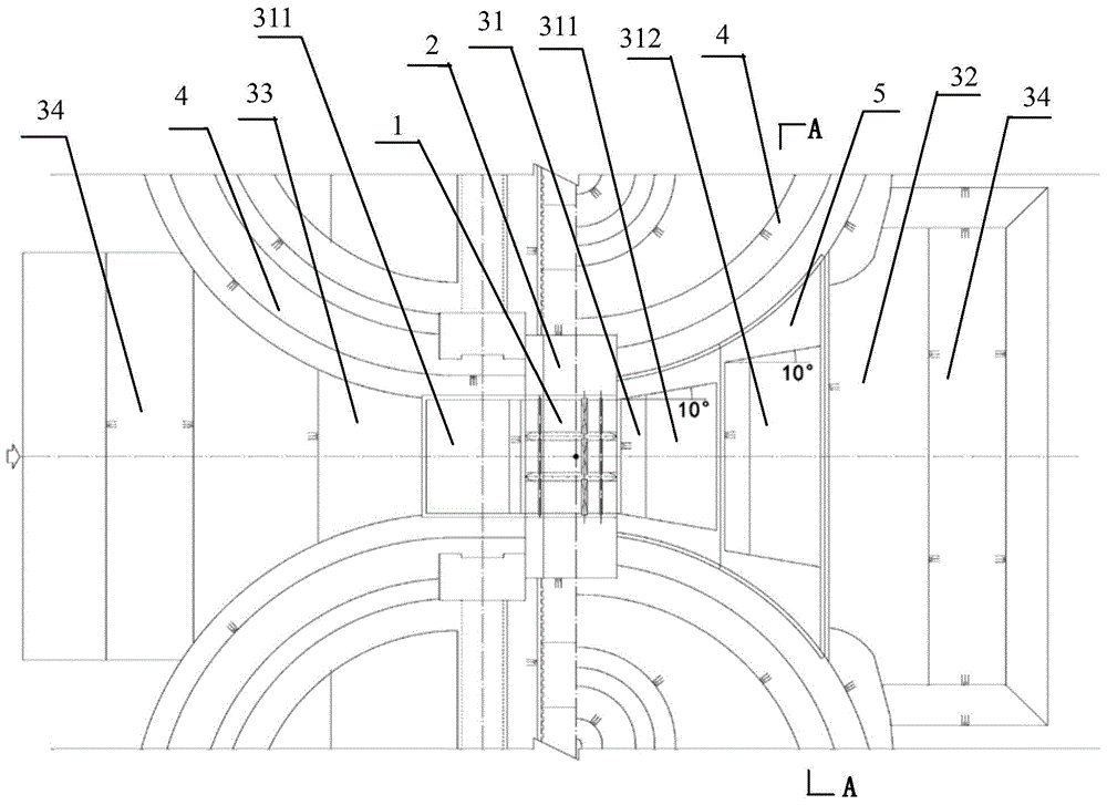
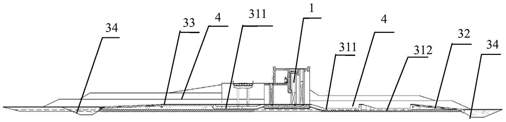
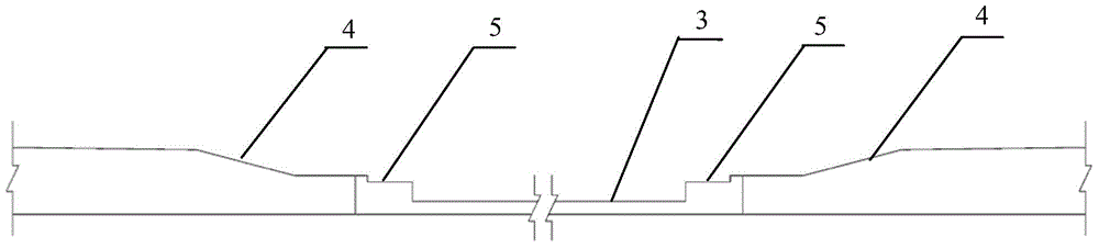
[0020] Embodiment 1: as figure 1 , figure 2 , image 3 As shown, a wingless wall sluice layout form includes a lock chamber 1, a quay wall 2, an energy dissipation and anti-scour facility 3, a slope protection 4, and a concrete platform 5; the energy dissipation and anti-scour facility 3 includes a stilling pool 31, a sea diffuser 32. Bottom protection 33, anti-scouring groove 34; the stilling pool upstream of the lock chamber is provided with a primary stilling pool 311, and the stilling pool downstream of the lock chamber is provided with a primary stilling pool 311 and a secondary stilling pool 312; 1 The anti-scour trough 34, the bottom protection 33, and the primary stilling basin 311 are arranged in the upstream along the flow direction of the water in sequence, and the primary stilling basin 311, the secondary stilling basin 312, the seaman 32, and the anti-scour Slot 34. The left bank of the upstream of the sluice, the right bank of the upstream of the sluice, the ...

Embodiment 2

[0021] Embodiment 2: as Figure 4 As shown, a layout form of a wingless wall sluice includes a sluice chamber 1, a quay wall 2, an energy dissipation and anti-scour facility 3, a slope protection 4, a concrete platform 5, and a wing wall 6; the energy dissipation and anti-scour facility 3 includes Pool 31, sea mantle 32, bottom protection 33, and anti-scouring groove 34; anti-scouring groove 34, bottom protection 33, and primary stilling pool 311 are arranged in sequence along the flow direction upstream of the lock chamber 1, and primary stilling pool 311 is arranged in sequence along the flow direction downstream Pool 311, secondary stilling pool 312, sea diffuse 32, anti-scouring groove 34. The difference from Example 1 is that wing walls 6 are set on the left and right banks upstream of the sluice, and slope protection 4 is installed on the left and right banks downstream of the sluice without wing walls 6, and slope protection 4 is arranged against the bank wall 2, and sl...


PUM


Abstract

This invention discloses a wingless wall water gate arrangement mode. According to the mode, a gate chamber, bank walls and energy dissipation and scouring prevention facilities are used, wherein the bank walls are arranged on the left side and the right side of the gate chamber, the energy dissipation and scouring prevention facilities are arranged on the upstream and the downstream of the gate chamber respectively, wing walls located at any one or several positions of the upstream left bank, the upstream right bank, the downstream left bank and the downstream right bank of a water gate are removed, and slope type revetments are arranged due to changes, abut against the bank walls and diffuse outwards. Due to the mode, scouring under the gate is effectively reduced, investment is saved, the construction period is shortened and construction difficulty is lowered.

Description

technical field [0001] The invention relates to an arrangement form of a sluice on a tidal soft soil foundation in a water conservancy project, in particular to an arrangement form of a sluice without a wing wall. Background technique [0002] According to the sluice code, the upstream and downstream layout of the conventional sluice chamber is generally a stilling basin, apron, sea diffuser, and anti-scouring groove, and vertical wing walls are generally used on the left and right. The projected length of the wing wall along the flow direction of the water should be greater than or equal to the length of the stilling basin, and the elevation of the top of the wall should be higher than the most unfavorable operating water level, so as to prevent the discharged water from overflowing from the top of the wall to the stilling basin, increasing the single-width flow and affecting energy dissipation Effect. If a figure-eight wing wall is used, the plane diffusion angle is gener...

Claims


Application Information

Patent Timeline
IPC IPC(8): E02B5/00E02B5/08
CPCE02B5/00E02B5/08
Inventor 袁文喜吴蕾包纯毅林登荣许吉骆康美包中进陆益挺李水泷刘敏虹
Owner 浙江省水利水电勘测设计院有限责任公司
Why Eureka
Try Eureka