Aeration type curve ladder energy dissipater in flood discharge hole
A technology for flood discharge tunnels and energy dissipators, applied in water conservancy projects, sea area projects, coastline protection, etc., can solve the problems of difficult adjustment of flow patterns, reduce engineering investment, reduce engineering volume, etc., and achieve convenient and simple body design and construction , Reduce engineering investment and reduce the effect of outlet velocity
- Summary
- Abstract
- Description
- Claims
- Application Information
AI Technical Summary
Problems solved by technology
Method used
Image
Examples
Embodiment 1
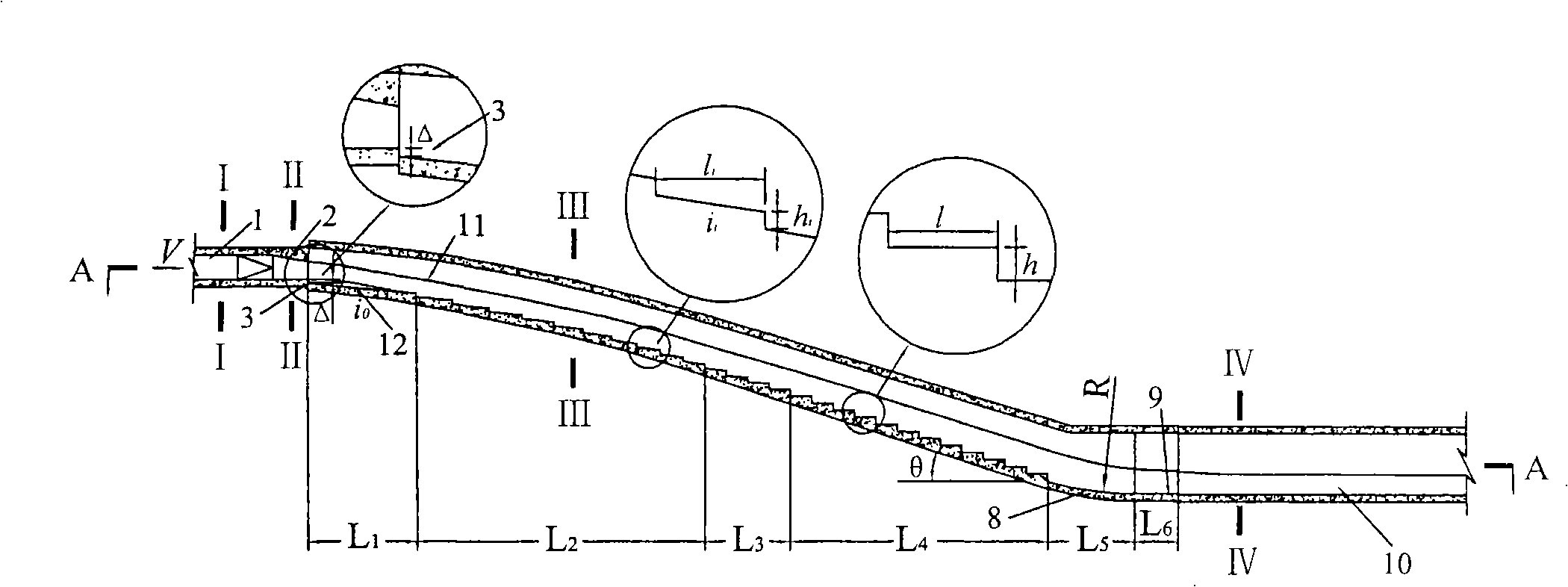
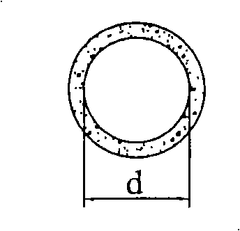
[0032] In this embodiment, the aeration-type curved ladder energy dissipator in the spillway tunnel is used for the curved connection between the upstream pressurized tunnel (empty tunnel) 1 and the downstream spillway tunnel 10 . The pressurized tunnel (vent) 1 is parallel to the downstream spillway 10, and the elevation difference between them is about 28m; the diameter d of the pressurized tunnel (vent) 1 is 3.5m, and the maximum flow Q=190m 3 / s, maximum single width flow q=54m 3 / s.m, pressure slope 2 is set at the exit, and the section gradually changes from circular to rectangular (see image 3 , Figure 4 ), the width B of the rectangular section 1 =2.5m, height H 1 =2.25m; the section of the curve connecting the cave is as follows Figure 5 shown, its width B 2 = 3.5m, the height H of the straight wall of the side wall 2 =5.0m, the maximum flow velocity at its inlet V=30m / s; the section of the downstream spillway is as follows Figure 6 shown, its width B 3 =7...
Embodiment 2
[0036] In this embodiment, the aeration-type curved ladder energy dissipator in the spillway tunnel is used for the curved connection between the upstream spillway tunnel (open channel) 1 and the downstream spillway tunnel 10 . The upstream flood discharge tunnel 1 and the downstream flood discharge tunnel 10 are parallel to each other, and the elevation difference between them is about 42m; the section of the upstream flood discharge tunnel 1 is as follows: Figure 9 shown, its width B 1 = 3.0m, the height H of the straight wall of the side wall 1 =5.0m, the maximum flow Q=210m 3 / s, maximum single-width flow rate q=70m 3 / s.m; the section of the curve connecting the cave body is as follows Figure 10 shown, its width B 2 = 4.0m, the height H of the straight wall of the side wall 2 =8.0m, the maximum flow velocity at its inlet V=35m / s; the section of the downstream spillway is as follows Figure 11 shown, its width B 3 = 7.0m, the height H of the straight wall of the s...
PUM
 Abstract
Description
Claims
Application Information
 - R&D
- Intellectual Property
- Life Sciences
- Materials
- Tech Scout
- Unparalleled Data Quality
- Higher Quality Content
- 60% Fewer Hallucinations
Browse by: Latest US Patents, China's latest patents, Technical Efficacy Thesaurus, Application Domain, Technology Topic, Popular Technical Reports.
© 2025 PatSnap. All rights reserved.Legal|Privacy policy|Modern Slavery Act Transparency Statement|Sitemap|About US| Contact US: help@patsnap.com


