
Cryogenic fluid electromagnetic valve

A low-temperature fluid and solenoid valve technology, applied in the direction of valve lift, valve details, valve devices, etc., can solve problems such as leakage and unreliable work, and achieve the effects of reliable work, convenient processing and long service life

Inactive Publication Date: 2009-01-21
浙江省医疗器械研究所
View PDF0 Cites 5 Cited by
  • Summary
  • Abstract
  • Description
  • Claims
  • Application Information

AI Technical Summary

Problems solved by technology

[0004] The solenoid valve with the above structure generally relies on the tension of the spring to press down on the valve core when it is in the off state, and the delivered fluid has a certain pressure, which will exert an upward force on the valve core at the liquid inlet. The force exceeds the tension of the spring, the fluid will push the valve core up, and part of the fluid will flow out from the liquid outlet, causing leakage and unreliable work

Method used


Image

  • Cryogenic fluid electromagnetic valve

Examples


Embodiment Construction

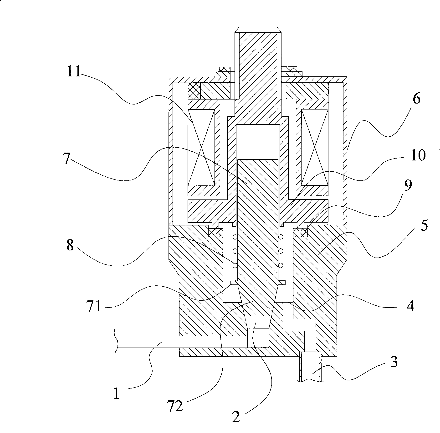
[0014] Such as figure 1 The low-temperature fluid solenoid valve shown includes a valve seat 5 and a valve cover 6 covering the valve seat. The valve cover 6 is provided with a coil seat 10, and a sealing ring 9 is placed between the coil seat 10 and the valve seat 5. The sealing ring 9 can be made of materials such as plastics and rubber. A coil 11 is wound around the coil seat 10, and a lifting chamber is arranged in the coil seat 10, and a valve core 7 is housed in the lifting chamber.

[0015] Spool 7 can use Cr 13 Al 4 Made of Nb magnetic stainless steel, a protruding ring 71 is arranged on it, and a spring 8 is sleeved between the protruding ring 71 and the coil seat 10 . The lower end of the valve core 7 is a rounded frustum-shaped sealing portion 72, and a circular liquid outlet 2 is opened at a corresponding position on the valve seat 5. The diameter of the liquid outlet 2 is larger than the diameter of the lower end of the rounded frustum-shaped sealing portion 72...


PUM


Abstract

Disclosed is a low-temperature fluid electromagnetic valve, which relates to a fluid valve structure. The prior art has shortages of poor sealing and unreliable operation. A fluid inlet is arranged on the inner wall of a cavity of a valve seat, the fluid inlet is connected with a fluid inlet pipe, a fluid outlet is also arranged on the inner wall of the cavity of the valve seat, the fluid outlet is connected with a fluid outlet pipe, a valve core which can perform lifting operation to control the open and close states of the fluid outlet is arranged in the electromagnetic valve, and an elastic piece is arranged between the valve core and a coil seat. The sealing is efficiently improved by improving the positions of the fluid inlet and the fluid outlet of the electromagnetic valve, and reliable operation, convenient process and long service life of the electromagnetic valve are guaranteed.

Description

【Technical field】 [0001] The invention relates to a fluid valve structure, in particular to a low-temperature fluid electromagnetic valve. 【Background technique】 [0002] The delivery of cryogenic fluids (such as liquid nitrogen, liquid oxygen, etc.) is involved in fields such as bioengineering, medical applications, and engine cooling, and solenoid valves are usually used to control the flow of fluids. [0003] The existing cryogenic fluid solenoid valve generally includes a valve seat and a coil seat. There is a cavity in the valve seat, and the liquid inlet is opened at the center of the bottom of the cavity. The valve core and the liquid outlet are arranged at other positions on the side wall or the bottom of the cavity, and the liquid inlet and the liquid outlet are respectively connected to the liquid inlet and the liquid outlet. When it is in the off state, the lower end of the spool presses the liquid inlet tightly to block the fluid flow; when it is opened, the val...

Claims


Application Information

Patent Timeline
IPC IPC(8): F16K1/00F16K31/06
Inventor 吕维敏章忠敏郭春娥
Owner 浙江省医疗器械研究所
Features
  • Generate Ideas
  • Intellectual Property
  • Life Sciences
  • Materials
  • Tech Scout
  • Unparalleled Data Quality
  • Higher Quality Content
  • 60% Fewer Hallucinations
Learn More