Liquefied gas supply system and method thereof
一种供给系统、液化气的技术,应用在管道系统、容器填充方法、容器排放的方法等方向
- Summary
- Abstract
- Description
- Claims
- Application Information
AI Technical Summary
Problems solved by technology
Method used
Image
Examples
Embodiment 1
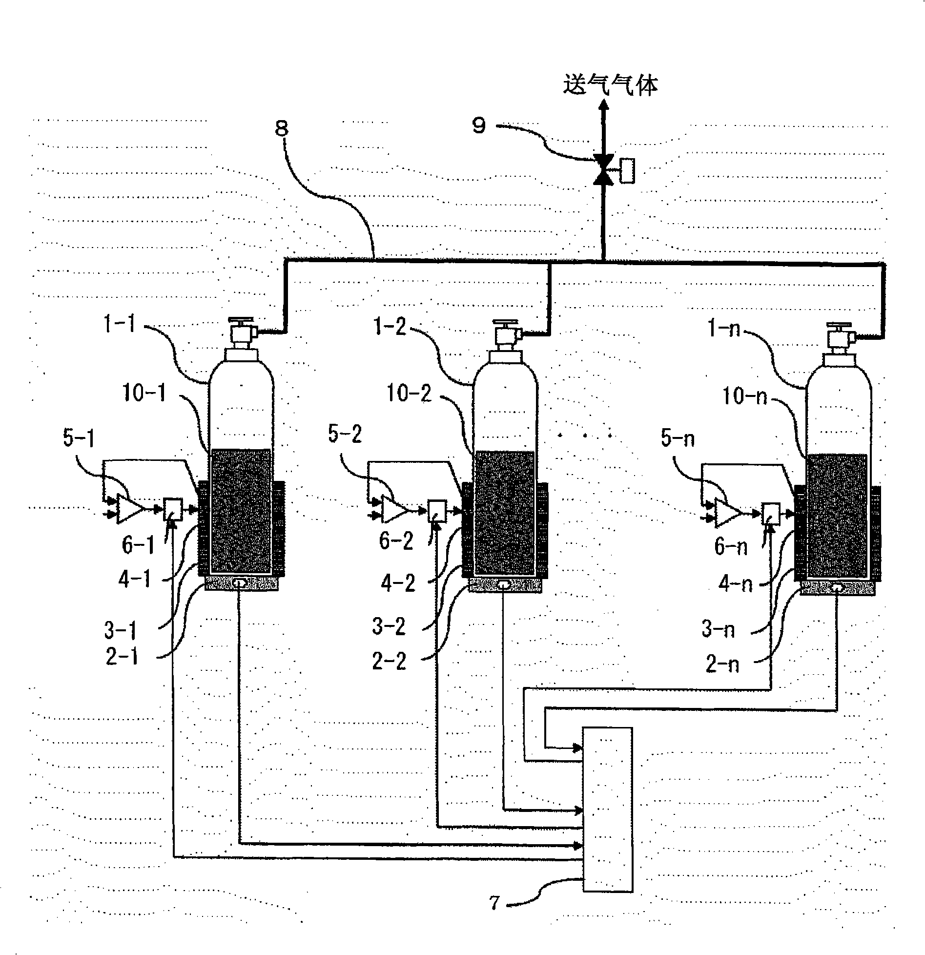
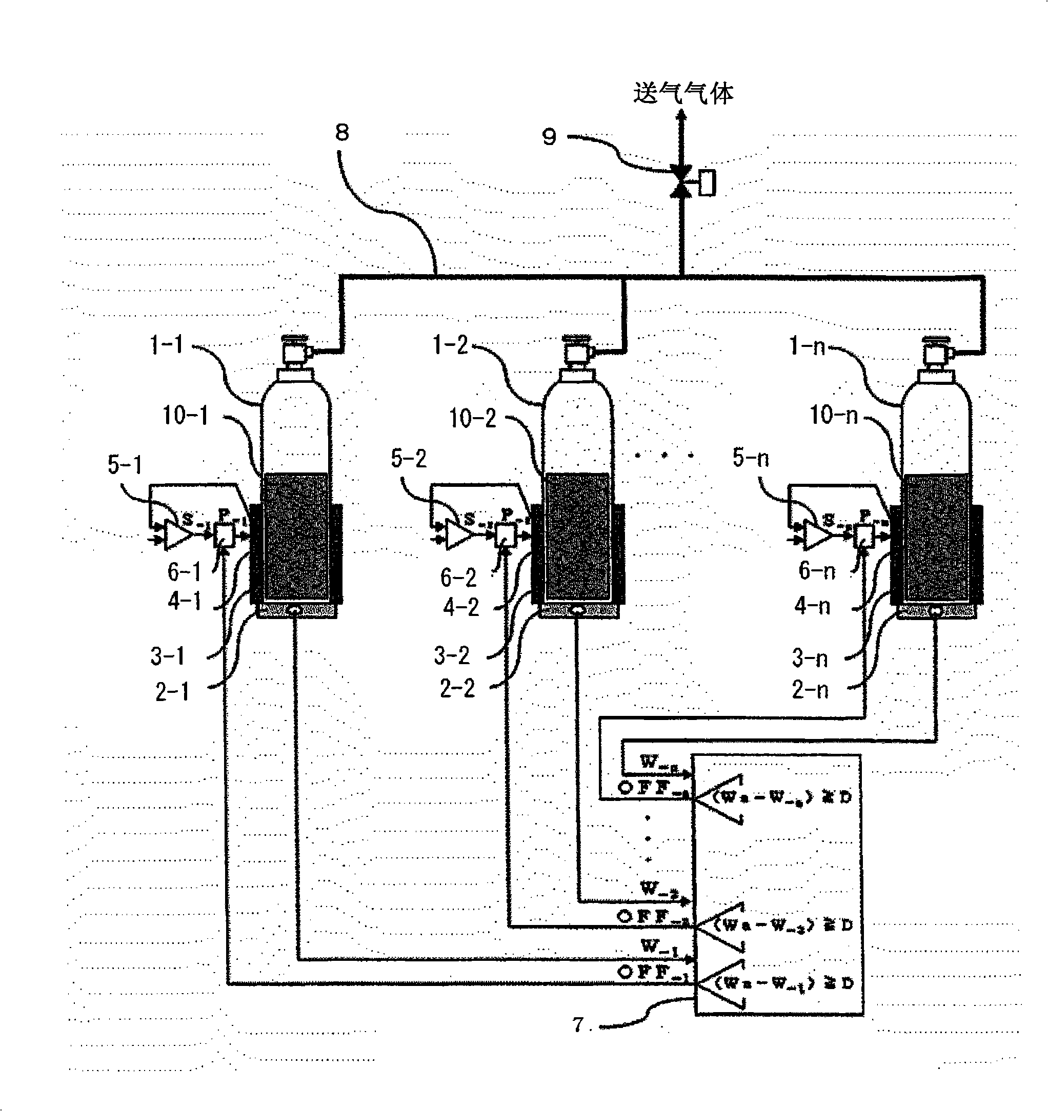
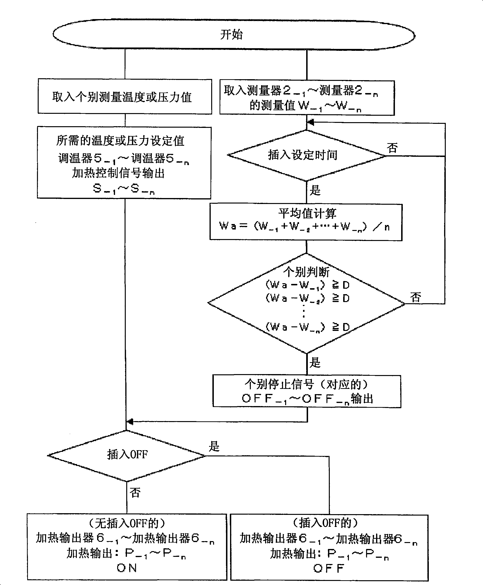
[0044] figure 1 It is a figure which shows the structure of Example 1 of the liquefied gas supply system concerning this invention. like figure 1 As shown, the liquefied gas supply system of the present invention is composed of the following: a plurality of (n) containers 1-1 to 1-n (with the first container being 1-1 and the nth container being 1-n additional labels to indicate, the same below); measuring device 2-1 ~ 2-n; heating source 3-1 ~ 3-n; heating amount measuring sensor 4-1 ~ 4-n; thermostat 5-1 ~ 5- n; heating output devices 6-1 to 6-n; measured value calculation comparator 7, connecting pipe 8, cut-off valve 9, and liquefied gas 10-1 to 10-n in each container.
[0045] Containers 1-1~1-n are containers of standard sizes that can be easily obtained, and their capacities are all the same. Before they are installed in this supply system, the amount of liquefied gas 10-1~10-n in each container is known (this embodiment 1 is weight). The containers 1-1 to 1-n are...
Embodiment 2
[0059] Figure 5 It is a figure which shows the structure of Example 2 of the liquefied gas supply system concerning this invention. replaces the above figure 1 The measuring devices 2-1 to 2-n in the container have liquid level sensors 11-1 to 11-n for detecting the liquid level (residual amount) of the liquefied gas as means for measuring the remaining amount of liquefied gas in the container. And, put the above figure 2 The measured values of a plurality of (n) measuring devices 2-1~2-n taken into the measured value calculation comparator 7 are replaced by L-1~L-n as liquid level sensors 11-1~11-n, so that The average value of all measured values calculated by the measured value calculation comparator 7 is La, the judgment value of the measured value calculation comparator 7 is D, and the stop signal output from the measured value calculation comparator 7 by this judgment is OFF-1 to OFF -n. and, in Figure 5 In , as an example of detecting the liquid level, a fl...
Embodiment 3
[0063] Image 6 It is a figure which shows the structure of Example 3 of the liquefied gas supply system concerning this invention. its to the above figure 1 Connection shutoff valves 12-1 to 12-n are added.
[0064] Refer to the following Image 6 Example 3 will be described. The operation in the normal supply state and the above figure 1 , figure 2 As explained, in the state where each container is connected, it is not necessarily in the supply state, the liquefied gas does not necessarily decrease, and there are cases where the consumption side stops, the flow of the supply gas supply is interrupted for a long time, or the shut-off valve 9 is closed and it is on standby. Case.
[0065] In this state, the liquefied gas in each container is repeatedly moved and filled from the high pressure to the low pressure between the containers due to the slight difference in vapor pressure caused by the different temperature, so as to keep the balance. Especially when the cut-of...
PUM
 Abstract
Description
Claims
Application Information
 - R&D
- Intellectual Property
- Life Sciences
- Materials
- Tech Scout
- Unparalleled Data Quality
- Higher Quality Content
- 60% Fewer Hallucinations
Browse by: Latest US Patents, China's latest patents, Technical Efficacy Thesaurus, Application Domain, Technology Topic, Popular Technical Reports.
© 2025 PatSnap. All rights reserved.Legal|Privacy policy|Modern Slavery Act Transparency Statement|Sitemap|About US| Contact US: help@patsnap.com


