Inserted terminal position of switch
A terminal device and switch technology, applied in the direction of switch terminals/connections, electrical components, circuits, etc., can solve problems such as costing a lot of man-hours, and achieve the effect of maintaining stability
- Summary
- Abstract
- Description
- Claims
- Application Information
AI Technical Summary
Problems solved by technology
Method used
Image

Examples
Embodiment approach 1
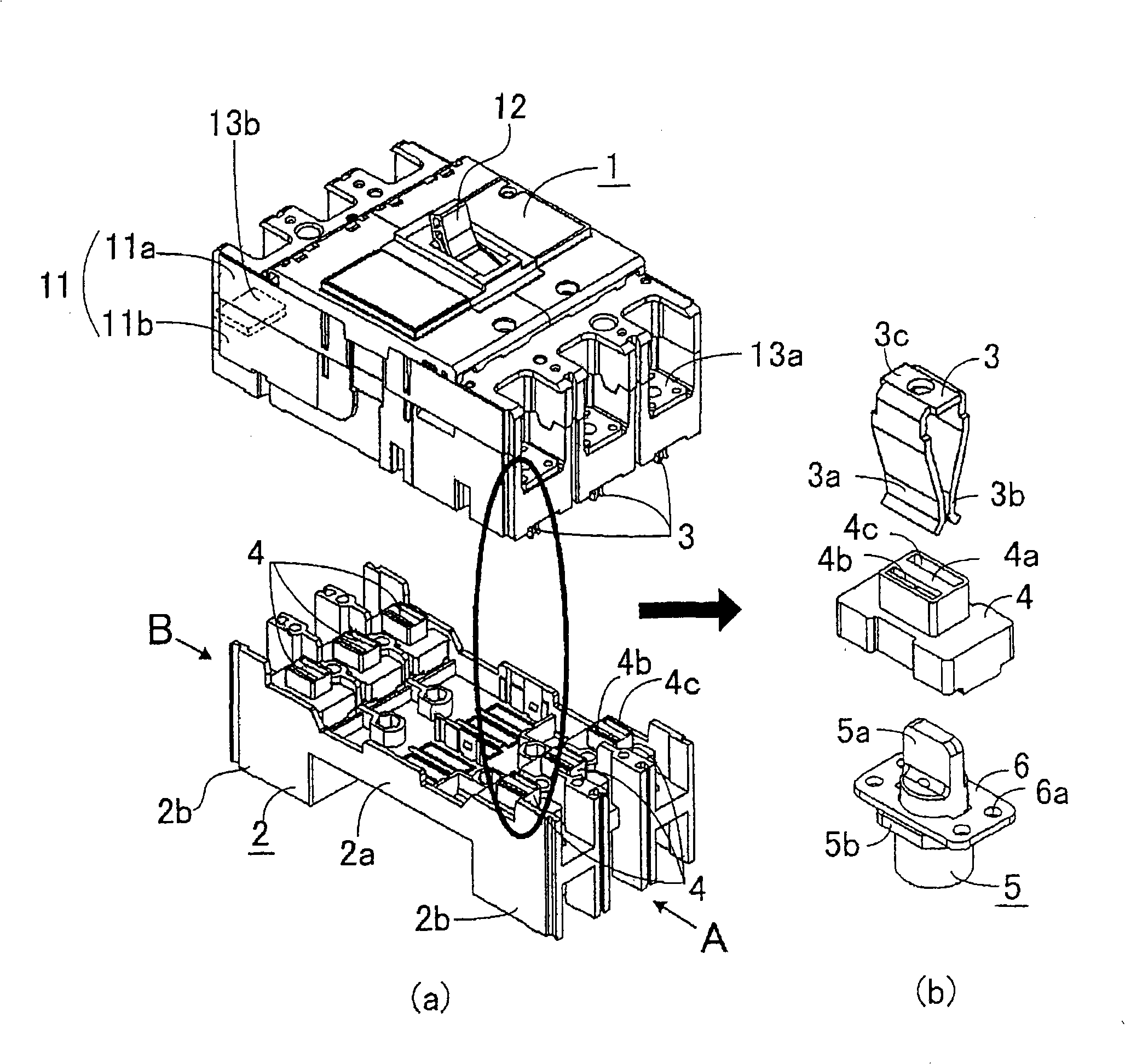
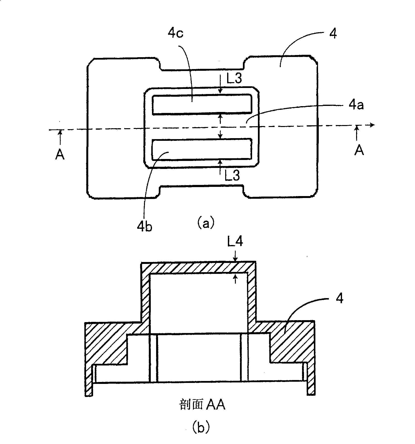
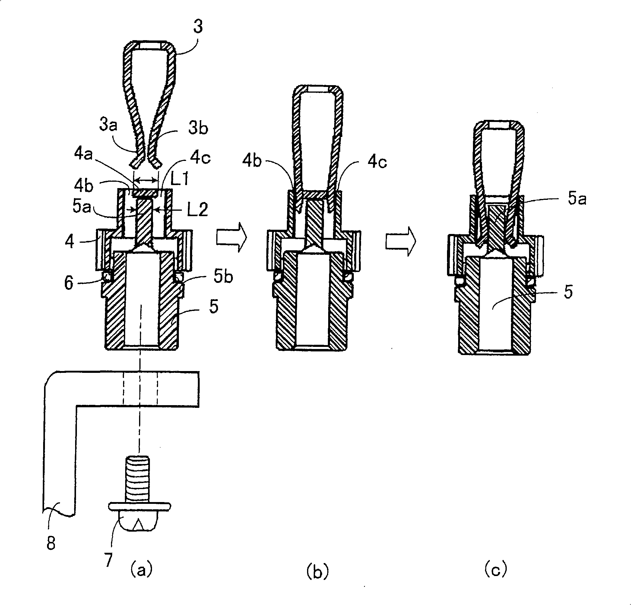
[0019] figure 1 (a) is a perspective view showing the appearance of the plug-in terminal device of the switch in the state before the switch and the plug-in terminal base are combined in the first embodiment of the present invention, figure 1 (b) is a diagram showing the clamping terminal installed on the switch side, and the terminal and terminal cover installed on the side of the insertion terminal block after being pulled out. In addition, figure 2 (a) Yes figure 1 (b) The top view of the terminal cover, figure 2 (b) Yes figure 2 (a) A-A line cross-sectional view. image 3 Yes means figure 1 (a) A cross-sectional view of the clamping terminal insertion process.
[0020] in figure 1 Here, 1 is a switch including a circuit breaker such as a circuit breaker for wiring or a leakage circuit breaker, and 2 is an insertion terminal block that is pre-arranged on a panel (not shown) or the like of a switchboard. The known switch 1 is formed by an insulating housing 11, which is...
Embodiment approach 2
[0029] Figure 4 Is in the second embodiment of the present invention and figure 2 Quite a picture. As mentioned in the background art section, due to the "plug-in type", it is estimated that the number of plug-in and unplugging will increase. That is, as described in the first embodiment, it is required to ensure durability and maintain high strength of the partition portion 4a that abuts the tip portions of the first pressure contact piece 3a and the second pressure contact piece 3b. So like Figure 4 As shown, by making the thickness of the partition 4a, for example, figure 2 (b) Compared to about 2 times, the plate thickness is thicker than other parts. At the same time, a thickness adjustment part (commonly referred to as R) is provided on the part corresponding to the top wall of the partition 4a, so as to achieve the above-mentioned contact The intensity compensation, prolong life.
Embodiment approach 3
[0031] Figure 5 (a) is an external perspective view of a terminal cover in Embodiment 3 of the present invention, Figure 5 (b) is its cross-sectional view. Since the number of insertions and removals increases as described in the second embodiment, it is preferable to improve the slidability of the clamping terminal 3 with respect to the terminal cover 4. So like Figure 5 As shown, the partition 4a is not the so-called plane shown before, but has a substantially triangular cross-section, that is, an inclined surface 4d is provided opposite to the pair of insertion ports 4b, 4c, and at the same time is placed on the top wall of the partition 4a. Place chamfer 4e. Based on this, it is possible to reduce the force from the first crimping piece 3a and the second crimping piece 3b that the partition portion 4a receives when inserting and removing the clamping terminal 3, and the quality stability can be further improved.
PUM
 Abstract
Description
Claims
Application Information
 - R&D
- Intellectual Property
- Life Sciences
- Materials
- Tech Scout
- Unparalleled Data Quality
- Higher Quality Content
- 60% Fewer Hallucinations
Browse by: Latest US Patents, China's latest patents, Technical Efficacy Thesaurus, Application Domain, Technology Topic, Popular Technical Reports.
© 2025 PatSnap. All rights reserved.Legal|Privacy policy|Modern Slavery Act Transparency Statement|Sitemap|About US| Contact US: help@patsnap.com