Supercharge Your Innovation With Domain-Expert AI Agents!

Lens barrel and imaging apparatus

A lens barrel and lens group technology, applied in installation, optics, instruments, etc., can solve the problems of limiting zoom magnification design specifications, reducing the degree of freedom of design, etc., to improve image quality, reduce tilt, and simplify the mechanism. Effect

Inactive Publication Date: 2009-01-28
SONY CORP
View PDF2 Cites 5 Cited by
  • Summary
  • Abstract
  • Description
  • Claims
  • Application Information

AI Technical Summary

Problems solved by technology

[0008] However, when such two groups of lenses form a movable unit, each group of lenses does not move independently in the direction of the optical axis, so that design specifications such as zoom magnification are limited, resulting in a problem that the degree of freedom in design becomes smaller

Method used


Image

  • Lens barrel and imaging apparatus
  • Lens barrel and imaging apparatus
  • Lens barrel and imaging apparatus

Examples


Embodiment Construction

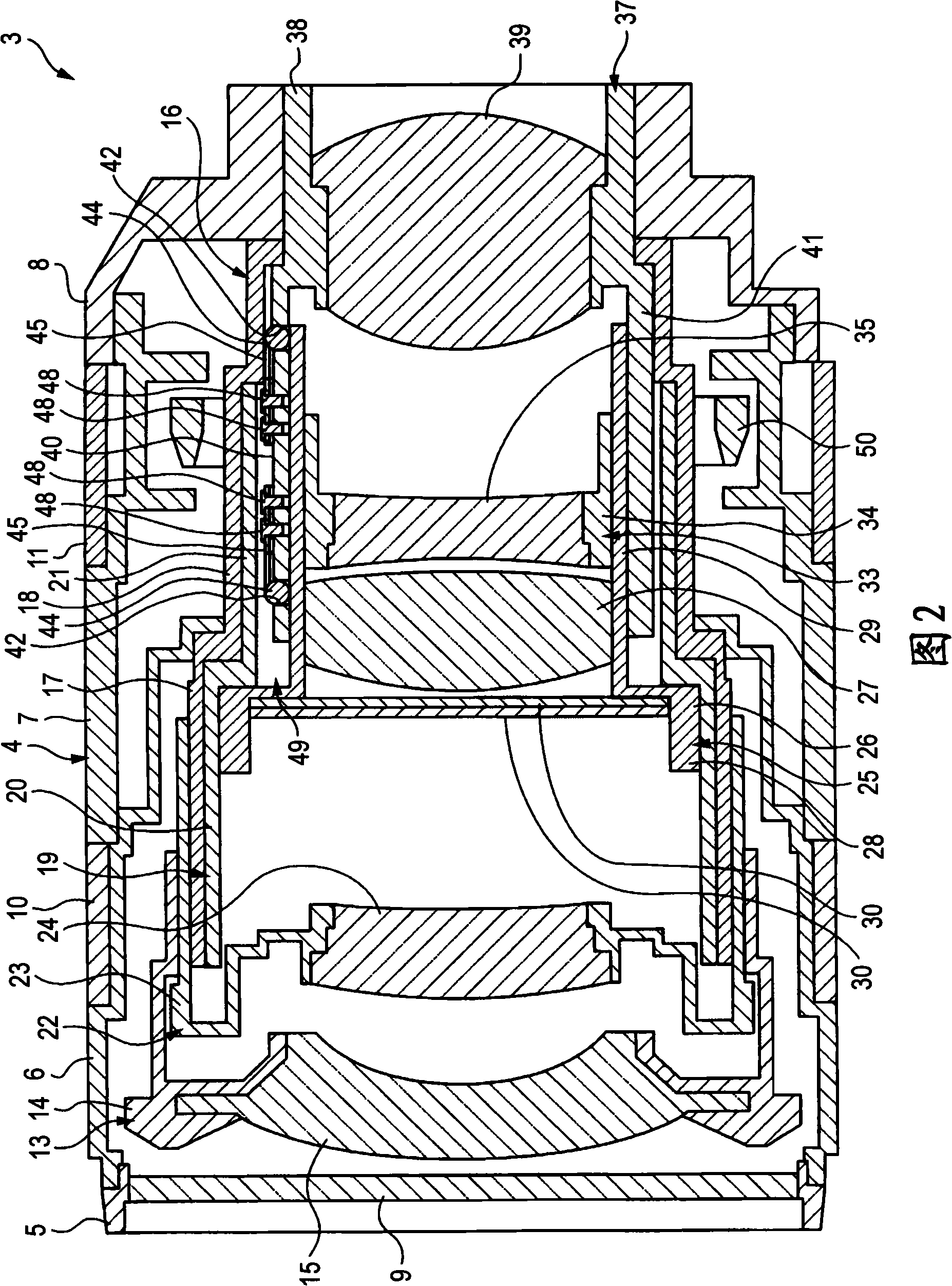
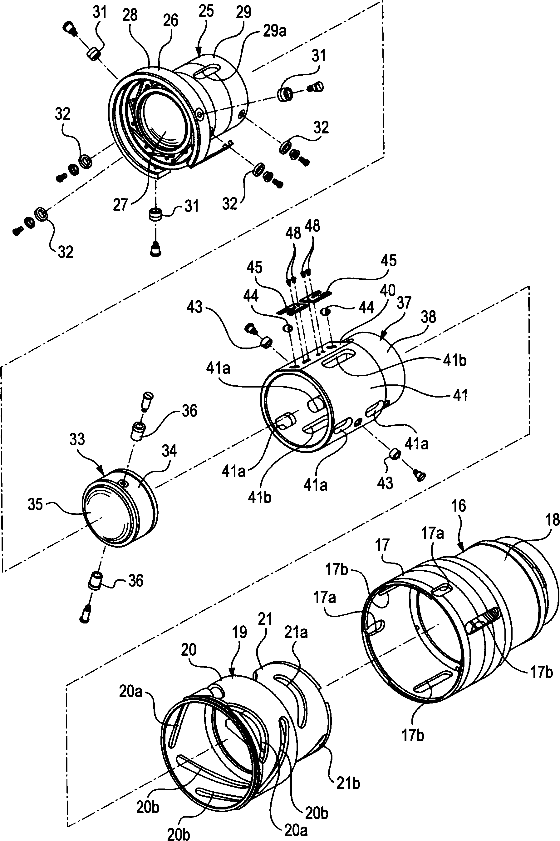
[0039] The best modes for realizing the lens barrel and the imaging device according to the embodiments of the present invention are described below with reference to the drawings.

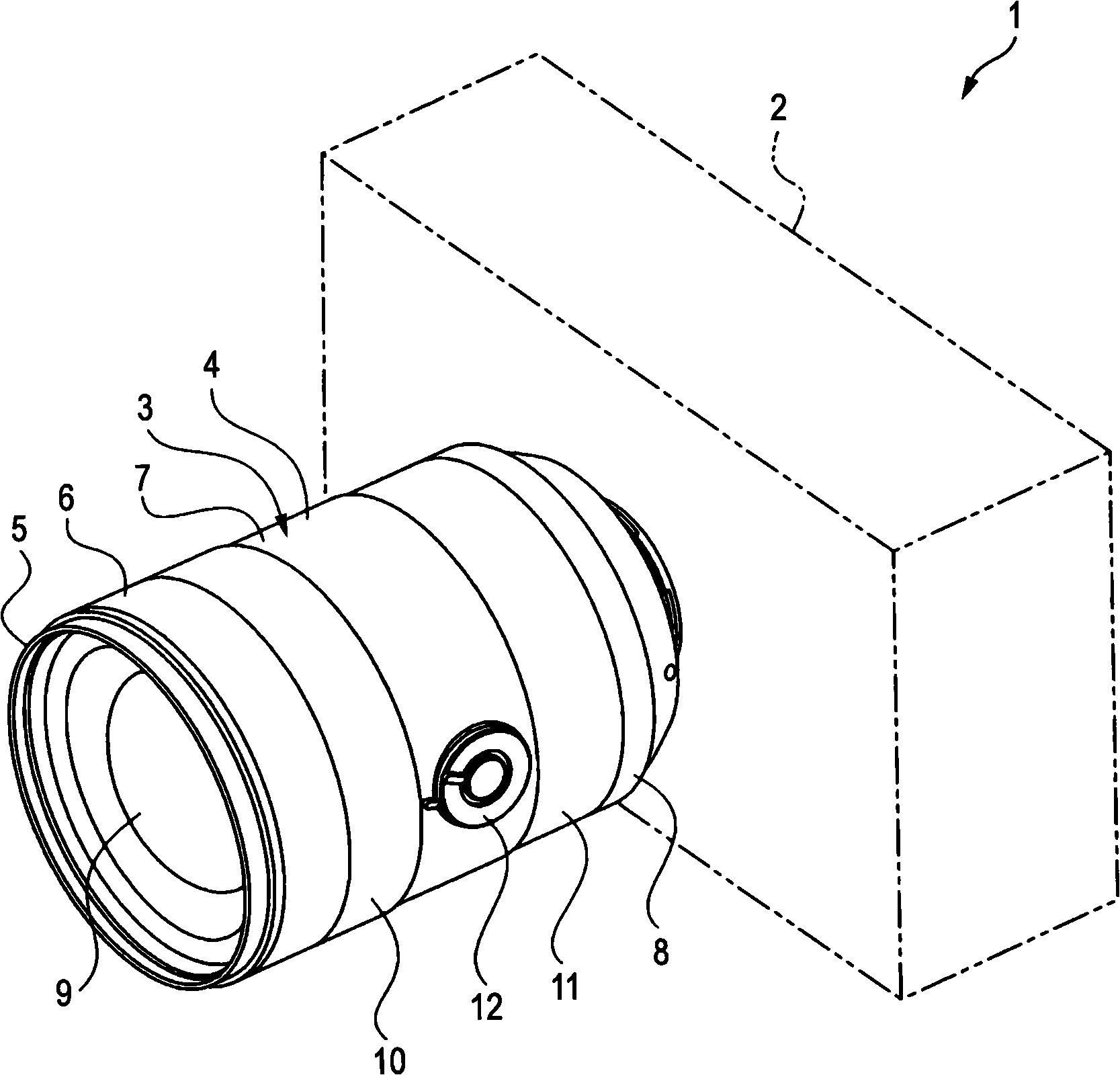
[0040] The best mode described below is an imaging device applied to a camera according to an embodiment of the present invention and a lens barrel according to an embodiment of the present invention applied to a lens barrel provided in the camera. However, the scope of the present invention is not limited to a camera or a lens barrel provided in the camera. For example, the optimum mode can be widely applied to various imaging devices included in video cameras or other devices or lens barrels provided in such various imaging devices.

[0041] In the following description, front-back, up-down, and left-right directions are defined with respect to a user who uses a camera to acquire an image. That is, the subject side is the front side, and the camera user side is the rear side.

[0042] Front-ba...


PUM


Abstract

A lens barrel in which a plurality of movable units, each including a group of lenses, are moved in the optical axis direction when a cam ring is rotated relative to a stationary ring around the optical axis, is disclosed. The lens barrel includes a first movable unit including a first group of lenses and a first moving frame having a roller support hole formed therein; a second movable unit including a second group of lenses and a second moving frame disposed inside the first moving frame; a pressing roller supported in the roller support hole in the first moving frame; a biasing spring attached to the outer surface of the first moving frame; and a receive roller supported by the first or second moving frame.

Description

[0001] Cross References to Related Applications [0002] The present invention contains subject matter related to Japanese Patent Application JP 2007-193510 filed in the Japan Patent Office on Jul. 25, 2007, the entire content of which is hereby incorporated by reference. technical field [0003] The present invention relates to the technical field of lens barrels and imaging devices, and more specifically, to the following technical field: wherein a biasing spring presses a pressing roller supported by a first movable frame against a second movable frame to prevent the lens group from moving toward The optical axis is tilted, for example to improve optical performance. Background technique [0004] Some imaging devices, such as still cameras and video cameras, include a lens barrel having multiple groups of lenses movable in the direction of an optical axis for focusing and zooming. [0005] Examples of such a lens barrel include a lens barrel previously assembled to a dev...

Claims


Application Information

Patent Timeline
Patent Type & Authority Applications(China)
IPC IPC(8): G02B7/04G02B7/02
CPCG02B7/102
Inventor 小山高志
Owner SONY CORP
Features
  • R&D
  • Intellectual Property
  • Life Sciences
  • Materials
  • Tech Scout
  • Unparalleled Data Quality
  • Higher Quality Content
  • 60% Fewer Hallucinations
Learn More