Installation structure for fuel injection valve and fuel injection system

A fuel injection system and fuel injection valve technology, which are applied to fuel injection devices, low-pressure fuel injection, and low-pressure fuel injection, etc., can solve the problems of insufficient fuel combustion and increase in fuel consumption.

Active Publication Date: 2009-02-04
DENSO CORP +1
View PDF10 Cites 8 Cited by
  • Summary
  • Abstract
  • Description
  • Claims
  • Application Information

AI Technical Summary

Problems solved by technology

Therefore, there is a problem that the combustion of fuel is insufficie

Method used


Image

  • Installation structure for fuel injection valve and fuel injection system
  • Installation structure for fuel injection valve and fuel injection system
  • Installation structure for fuel injection valve and fuel injection system

Examples


Embodiment Construction

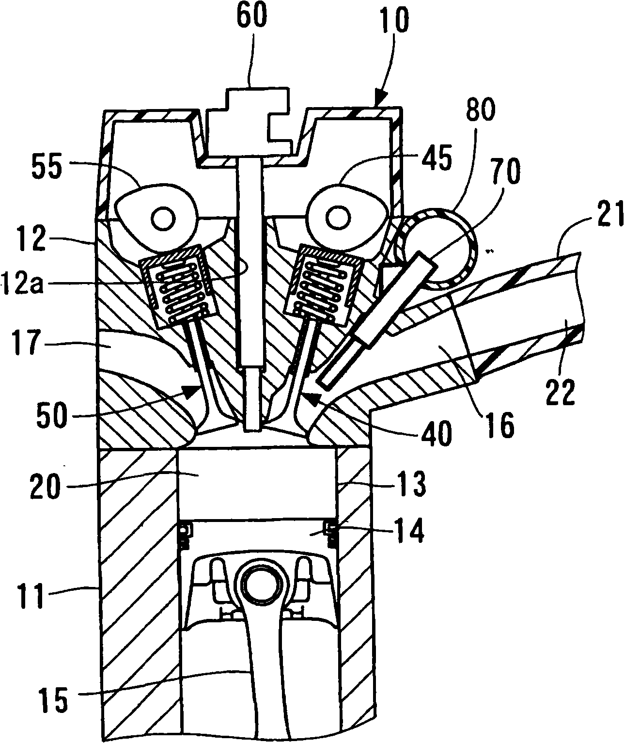
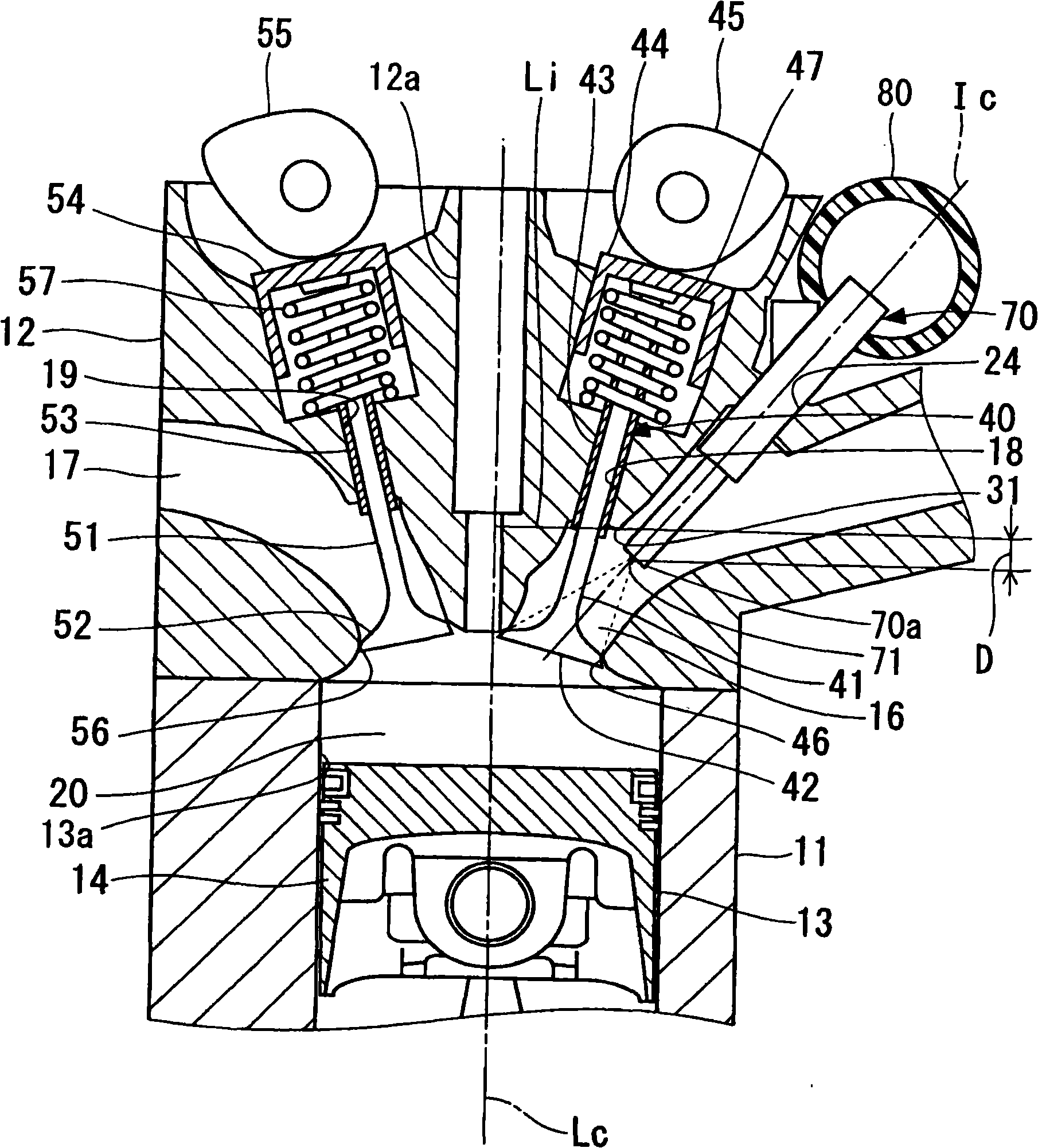
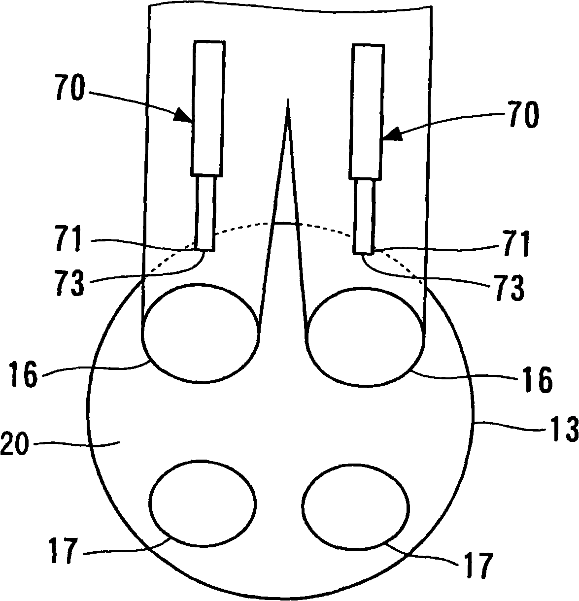
[0052] Hereinafter, the mounting structure of the fuel injection valve and the fuel injection system according to the first to fourth embodiments of the present invention will be described.

[0053] In the mounting structure of the fuel injection valve and the fuel injection system according to the first to fourth embodiments, the end portion of the fuel injection valve is a wall surface through which the intake valve protrudes out of the wall surfaces forming the intake port, and is located at an angle perpendicular to the The position overlaps with the imaginary plane of the central axis of the cylinder, or protrudes toward the combustion chamber side from the imaginary plane. Accordingly, it is possible to suppress the fuel injected from the fuel injection valve from adhering to the wall surface forming the intake port. As a result, insufficiently atomized fuel is suppressed from flowing into the fuel chamber. Thereby, the fuel injected from the fuel injection valve is suf...


PUM


Abstract

Provided is an mounting structure of a fuel injection valve and a fuel injection system. An end portion, on the combustion chamber side, of a fuel injection valve is projected from a position of a wall surface forming an intake port, whose position is superposed on an imaginary plane that passes a wall surface from which an intake valve projects and is normal to the center axis of a cylinder, or is projected from the imaginary plane to the combustion chamber side. Alternatively, the center of an end portion, on the fuel injection side, of a fuel injection valve for injecting fuel to intake air flowing in a branch port branched from an intake port is placed closer to the center axis side, in the radial direction of the cylinder, of a cylinder than to the center axis of an intake valve. Alternatively, an upstream side fuel injection valve injects fuel to intake air flowing at an intake port, and a down stream side fuel injection valve injects fuel to intake air flowing at a branch port branched from an intake port. Alternatively, the amount of injection of fuel is controlled for each fuel injection valve for injecting fuel to intake air flowing at a branch port branched from an intake port.

Description

[0001] Cross References to Related Applications [0002] The present invention requires Japanese patent applications 2006-89704 filed on March 29, 2006, 2006-89711 filed on March 29, 2006, 2006-89715 filed on March 29, 2006, and filed on May 16, 2006 No. 2006-136467 and the priority of No. 2007-70191 filed on March 19, 2007, and their disclosures are incorporated into this application by reference. technical field [0003] The present invention relates to a mounting structure of a fuel injection valve that injects fuel into intake air sucked into an internal combustion engine, and a fuel injection system. Background technique [0004] JP-2004-225598-A and its corresponding US-2004 / 0164187-A1, DE-2004003361-A1 disclose that each combustion chamber has a plurality of branch ports of the internal combustion engine (hereinafter referred to as the engine), flow through A fuel injection system that injects fuel into the intake air of each branch port. In the techniques disclosed...

Claims


Application Information

Patent Timeline
IPC IPC(8): F02M69/00F02M61/18F02M69/04
CPCY02T10/125
Inventor 富板幸生大村秀和中濑善博青木文明山下义典铃木健了
Owner DENSO CORP
Why Eureka
Try Eureka