
Card connector

A card connector and connector technology, applied in the direction of connection, instrument, device to prevent wrong connection, etc., can solve the problems of instability, poor contact between the card and the connector, movement, etc., and achieve the effect of eliminating incomplete connection.

Inactive Publication Date: 2009-02-11
MEA TECH PTE
View PDF2 Cites 0 Cited by
  • Summary
  • Abstract
  • Description
  • Claims
  • Application Information

AI Technical Summary

Problems solved by technology

Therefore, a card with a small size and a thin thickness is accommodated in an unstable state in the card receiving hole, and if some kind of impact is applied to the connector, it will easily move, and as a result, there will be a gap between the card and the connector. Causes poor contact, which becomes the cause of failure

Method used


Image

  • Card connector
  • Card connector
  • Card connector

Examples


Embodiment 1

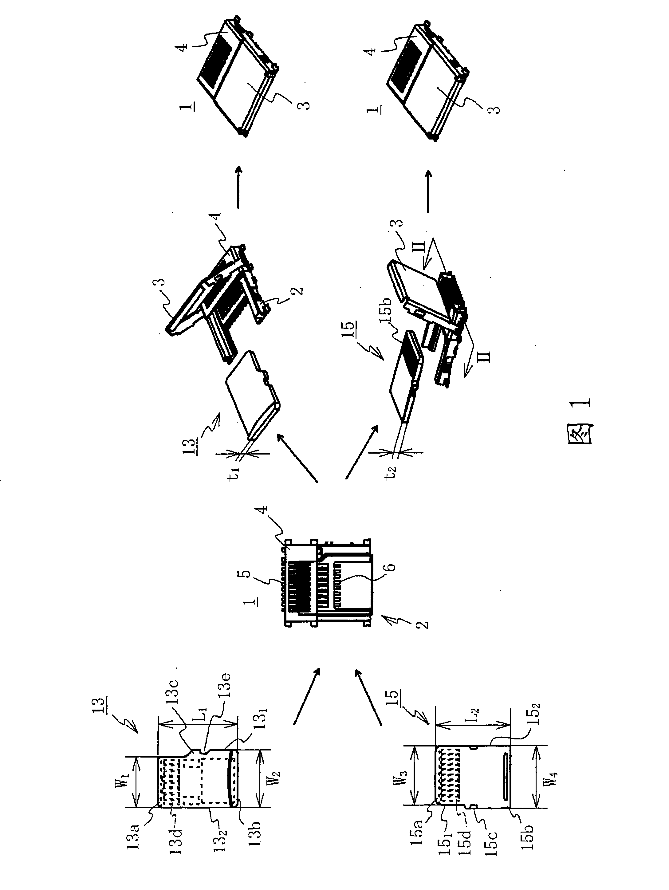
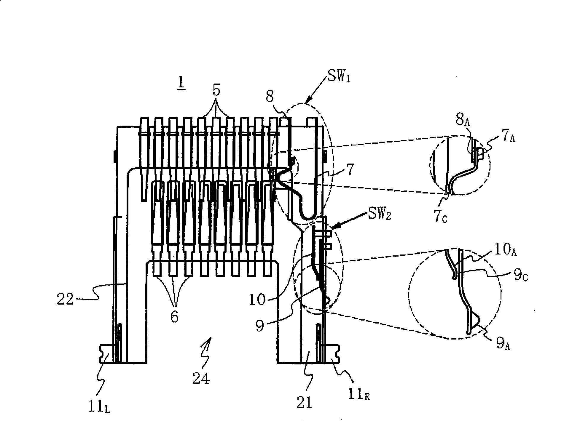
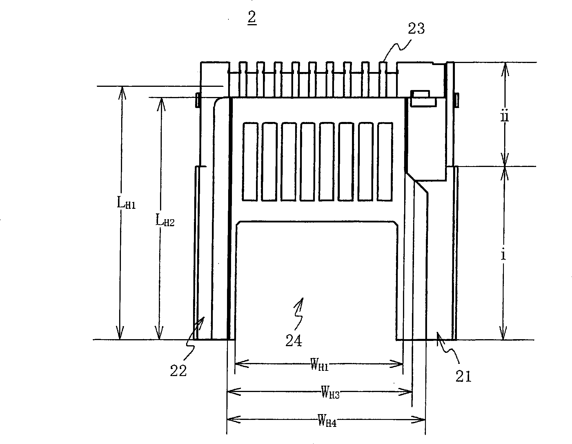
[0044] As shown in Figure 1, the card connector (hereinafter referred to as connector) 1 is suitable for two types of first and second cards with slightly different sizes and thicknesses, such as micro SD (Super Density) card 13 and micro MMC (Multi Media Card) card 15. In view of this, first, these cards will be briefly described.

[0045] Micro SD card 13 is L by the length of length direction 1 , The width of the front and rear ends 13a, 13b is W 1 , W 2 (W 1 2 ) and a thickness of t 1 The micro SD card 13 contains an IC chip inside, and its outer periphery is formed by molding an electrically insulating synthetic resin. On one side (first side) 13 of this micro SD card 13 sides 1 On the top, there are positioning protrusions 13c and locking grooves 13e, and the other side 13 2 is linear. In addition, on the surface of the micro SD card 13, a plurality of contacts 13d connected to an internal IC chip are provided.

[0046] The micro-MMC card 15 also has substantial...


PUM


Abstract

A card connector has: a connector housing constituted of electrical insulators and capable of housing cards inside a bottomed card holding cavity which is formed therein so as to be enclosed on three sides by an opposed pair of first and second frames and a third frame that links the end portions of the first and second frames, and so as to be open at the front and top. Contact terminals are deposed inside the connector housing's card holding cavity. An open-close cover covers the open portions of the connector housing's card holding cavity. The open-close cover has, at the front thereof where the card is installed, a sensing member that senses the installation status of the card. The rear of the open-close cover is rotatably pivoted on the first and second frames. After a card is installed inside the card holding cavity, the card's installation status is sensed by closing the open-close cover and positioning the sensing member of the open-close cover at the rear end portion of the card. The card connector is therefore arranged such that, when installing a card it is possible to examine the part where the card is installed, so that a card connector is provided in which cards of differing size and thickness, etc., can be installed reliably and in a simple manner.

Description

technical field [0001] The present invention relates to a card connector used for mounting on various electronic devices such as personal computers and portable terminals. with connectors. Background technique [0002] Regarding card connectors, for example, they are installed on various electronic devices such as personal computers and portable terminals, and are used to insert cards with built-in CPUs or memory ICs (integrated circuits), such as micro MMC (Multi Media Card: Multimedia Card) card or micro SD (Super Density: super high density) card and other small cards to expand the functionality of these devices. [0003] A representative example of such a card connector is disclosed in, for example, Patent Document 1 below. This card connector has: a connector housing with a card insertion port on the front and a card receiving hole inside; and a plurality of contact terminals installed in the card receiving hole. The connector has a structure in which two types of ca...

Claims


Application Information

Patent Timeline
Patent Type & Authority Applications(China)
IPC IPC(8): H01R27/00H01R12/16H01R13/64
CPCG06K7/0021
Inventor 孔焕焮梁永兴
Owner MEA TECH PTE
Learn More