Heating Panels and connection methods thereof

a technology of connection methods and heat exchangers, applied in the field of heat exchangers, can solve problems such as human health hazards

Pending Publication Date: 2022-09-22
WERTSBERGER SHALOM
View PDF0 Cites 0 Cited by
  • Summary
  • Abstract
  • Description
  • Claims
  • Application Information

AI Technical Summary

Problems solved by technology

Such liquids may cause short circuit, in certain case overheating at some areas, and potentially causing

Method used


Image

  • Heating  Panels and connection methods thereof
  • Heating  Panels and connection methods thereof
  • Heating  Panels and connection methods thereof

Examples


Embodiment Construction

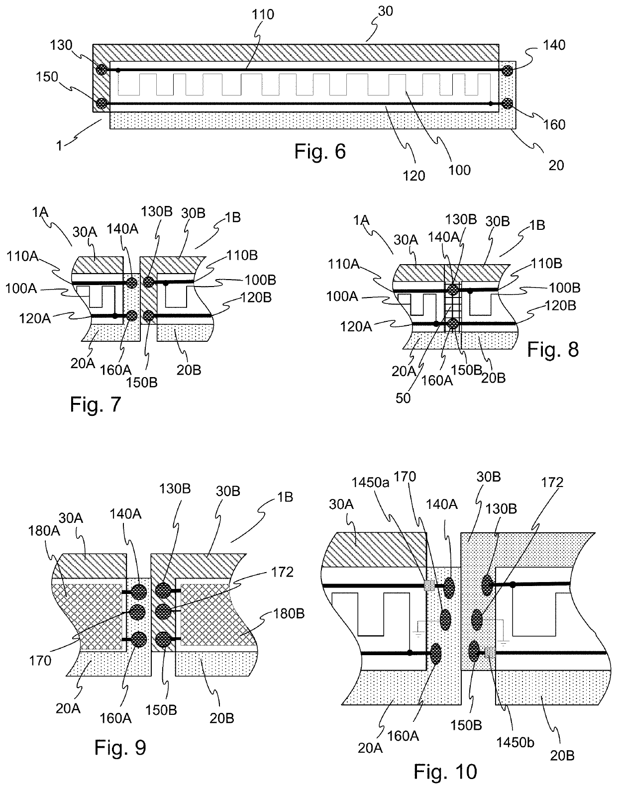
[0072]FIG. 6 depicts a simplified schematic view of an adhesive abutment type heating floor panel in accordance with an aspect of the invention. FIG. 6 depicts the heating panel 1 with a heating element 100 disposed between the upper and lower surfaces of the panel. The heating element is electrically coupled to two busbars 110, 120. The busbars are electrically coupled with respective contacts disposed in the abutments, for transmitting electrical power; busbar 110 is connected to contact 130 on the lower abutment 30, and to contact 140 on the upper abutment on the opposite end of the panel, and busbar 120 is electrically coupled to contact 150 on the lower abutment 30 and to contact 160 on the upper abutment 20.

[0073]The busbars may be made by any method and using any materials which would provide sufficiently low resistivity to carry the maximum current allowed for a row of consecutively connected panels, in accordance with a desired design criterion, while causing less voltage d...


PUM


Abstract

A floor panel having a heating element disposed therein, the floor panel having at least two abutments for operationally coupling the panel to adjacent panels. Electrical contacts are disposed on complementary abutments or abutment walls and busbars electrically couple between complementary contacts of opposing abutments such that, when adjacent floor panels are laid together to form a floor or a portion thereof, the busbars are able to feed power to heating elements disposed in the panel. The panel have sealants and/or adhesives which protect at least one contact from fluids. Also disclosed are connector bars, adapters, and switching and protection arrangements, and optional constructions for inter-panel connectors.

Description

FIELD OF THE INVENTION[0001]The present invention relates generally to heating panels such as floor panels or tiles, wall tiles and the like, and more specifically to heating panels with overlapping portions utilized connecting the panels as well as for providing electrical connection to the panel.BACKGROUND OF THE INVENTION[0002]Floor panels are oftentimes used nowadays for forming floors by adjoining numerous panels. Floor panels commonly support a scoff resistant and an aesthetically pleasing appearance at the top of the panel. Oftentimes the aggregation of adjoining floor panels forms a floor surface that is not directly adhered, nailed, or otherwise attached to the underlying surface, an arrangement colloquially known as a ‘floating floor’. In recent years engineered wood and laminated synthetic floor panels gained acceptance as an inexpensive and easy to install floor covering. Floor panels are available in numerous forms.[0003]Various methods of adjoining floating floor panel...

Claims


Application Information

Patent Timeline
IPC IPC(8): F24D13/02E04F15/02H05B1/02
CPCF24D13/024E04F15/02038E04F15/02016H05B1/0277E04F2201/0138E04F2201/023E04F2201/043E04F2290/023H05B2203/016Y02B30/00H05B2203/026H05B2203/011H05B3/06H05B2203/003H05B2203/013H05B3/267
Inventor WERTSBERGER, SHALOM
Owner WERTSBERGER SHALOM
Why Eureka
Try Eureka