
Contactless voltage transducer

a voltage transducer and contactless technology, applied in the field of transducers, can solve the problems of inconvenient access to ground connections, needing ground terminals, and inability to meet the requirements of measurement, and achieve the effect of accurate and reliable results

Active Publication Date: 2021-10-05
LEM INT SA
View PDF14 Cites 0 Cited by
  • Summary
  • Abstract
  • Description
  • Claims
  • Application Information

AI Technical Summary

Benefits of technology

The invention aims to provide a contactless voltage transducer that is accurate, reliable, safe, and easy to install. It should also be cost-effective to manufacture and install.

Problems solved by technology

A main drawback of the system described in U.S. Pat. No. 5,473,244, and also in other contactless voltage measurement systems such as described in U.S. Pat. No. 6,470,283, is the need to have a ground terminal.
Access to a ground connection at the position of installation of the voltage measurement transducer may not be readily available, and the need to install a galvanic connection increases the cost and complexity of the voltage measurement setup.
Moreover, for hazardous voltage applications, the need to implement a galvanic connection may increase risks to safety of personnel installing, maintaining or using the measurement equipment.

Method used


Image

  • Contactless voltage transducer
  • Contactless voltage transducer
  • Contactless voltage transducer

Examples


Embodiment Construction

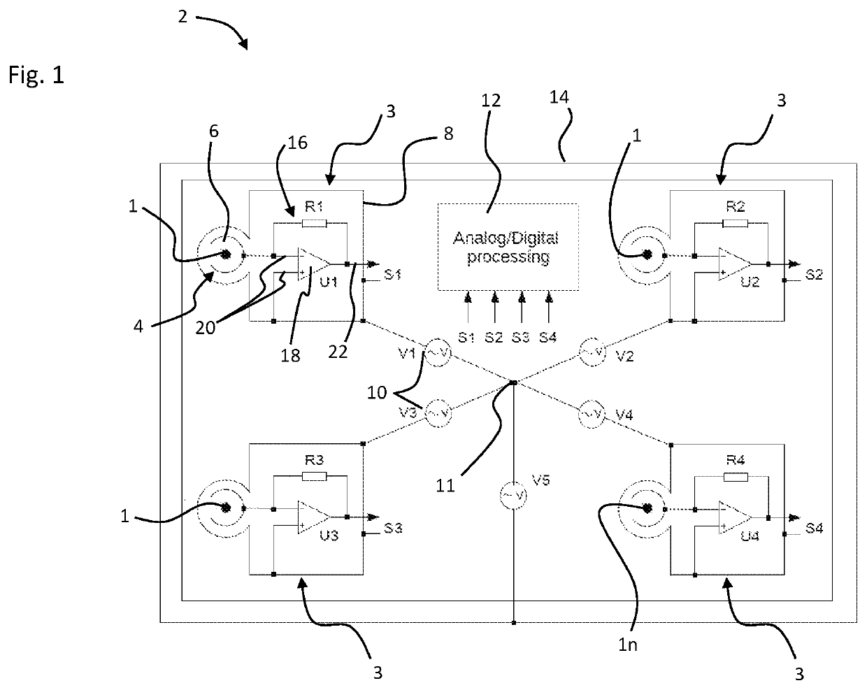
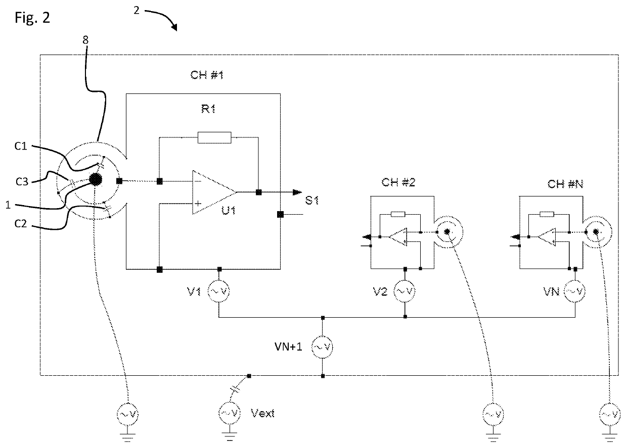
[0043]Referring to the figures, a contactless voltage transducer 2 according to an embodiment of the invention comprises two or more capacitive current measurement units 3, each comprising an electrode surrounding a passage 6 for receiving therethrough a respective conductor 1, 1n of a conductor system comprising at least two conductors, at least one of which carries an alternating voltage.

[0044]In an embodiment, the conductors of the conductor system may belong to a multi-phase alternating voltage electrical conduction system. The electrical conduction system may be two-phase, three phase or have four or more phases, and may comprise in additional a neutral conductor. It may however be noted that the invention is not limited to a multiphase system and may be applied to any conductors that exhibit a relative alternating voltage between measured conductors.

[0045]The conductors may for instance be in the form of conventional insulated wires or cables, or insulated conductor rods or ba...


PUM

PropertyMeasurementUnit
frequencyaaaaaaaaaa
frequencyaaaaaaaaaa
frequencyaaaaaaaaaa

Abstract

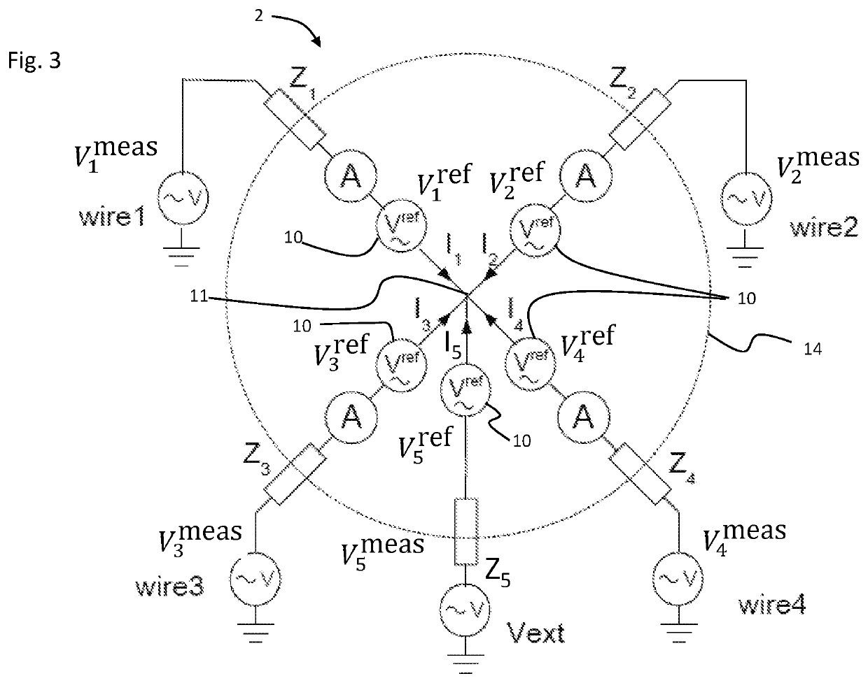
Contactless voltage transducer for measuring voltages between at least two conductors of an alternating voltage conductor system, the transducer including two or more capacitive current measurement units, each said capacitive current measurement unit comprisingan electrode surrounding a passage for receiving therethrough a respective said conductor of the alternating voltage conductor system,an electrode shield surrounding the electrode,an electrode signal processing circuit portion connected to the electrode and electrode shield, configured to output an analog measurement signal, anda reference voltage signal generator connected to the electrode shield and configured to generate a reference voltage source signal,wherein the reference voltage signal generators of the two or more capacitive current measurement units are connected together at a common floating voltage connection point.

Description

CROSS-REFERENCE TO RELATED APPLICATIONS[0001]The present application is a national stage entry of International (PCT) Patent Application Number PCT / EP2018 / 068620, filed Jul. 10, 2018, which in turn claims priority to European Patent Application No. 17181076.5, filed Jul. 12, 2017, the subject matter of which are expressly incorporated herein by reference.FIELD OF THE INVENTION[0002]This invention relates to a transducer for measuring alternating voltages in in a contactless manner.BACKGROUND OF THE INVENTION[0003]It is known to measure alternating (AC) voltages and relative phases between two to or more conductors (typically three phases and neutral) without interrupting and contacting the conductors. The conductors may for instance be in the form of electrical cables, and for instance a capacitive transducer with a split electrode is placed around each of the cables. The contactless transducer facilitates installation and decreases hazards to personnel and equipment, especially in ...

Claims


Application Information

Patent Timeline
Patent Type & Authority Patents(United States)
IPC IPC(8): G01R15/16G01R15/14G01R19/25G05F3/08H03M1/00
CPCG01R15/16G01R15/142G01R19/2513G05F3/08H03M1/001
Inventor BUHLMANN, FÉLIXSCHLÄFLI, DOMINIKTEPPAN, WOLFRAM
Owner LEM INT SA
Learn More