
LED lamp and driver shell for LED lamp

A technology of LED lamps and drivers, which is applied to semiconductor devices of light-emitting elements, parts of lighting devices, lighting and heating equipment, etc. It can solve problems such as complicated procedures, failure to meet high-voltage resistance requirements, and leakage, and achieve easy installation, Improve security and realize the effect of positioning

Pending Publication Date: 2017-05-10
CHENHUI GUANGBAO TECH CO LTD
View PDF10 Cites 0 Cited by
  • Summary
  • Abstract
  • Description
  • Claims
  • Application Information

AI Technical Summary

Problems solved by technology

[0003] During the working process, in order to ensure that the driver can provide the required stable voltage for the normal operation of the LED, the driver needs to be protected electrically and mechanically. The commonly used protection methods are: (1) Wrap the PET insulating material outside the driver. The protection method is not only complicated in process, but also the welding feet of the components on the driver PCB board are easy to pierce the insulating layer, resulting in leakage or failure to meet the high-voltage resistance requirements; In this protection method, the solder feet of components are easy to pierce the insulating layer, resulting in leakage or failure to meet the high voltage requirements, or the heat cannot be dissipated in time due to too tight packaging, which affects the service life of the driver; (3) Put the driver in In the plastic tube stretched from PC material, in this protection method, the driver needs to be fixed into the plastic tube with glue, and the gluing process is complicated and not environmentally friendly

Method used


Image

  • LED lamp and driver shell for LED lamp
  • LED lamp and driver shell for LED lamp
  • LED lamp and driver shell for LED lamp

Examples


Embodiment Construction

[0023] The present invention will be further described below in conjunction with embodiment and accompanying drawing.

[0024] The following embodiments are mainly aimed at the embodiment of the LED lamp of the present invention. Since the LED lamp of the present invention adopts the driver shell of the present invention, the description of the embodiment of the driver shell has been included in the description of the embodiment of the LED lamp.

[0025] The invention mainly aims at improving the structure of the driver shell for the LED lamp, and improves the use safety of the LED lamp while facilitating the installation of the driver. The following embodiments only illustrate the structure of the driver shell, and the lampshade, driver and lamp holder of the LED lamp can be designed according to existing products.

[0026] LED light embodiment

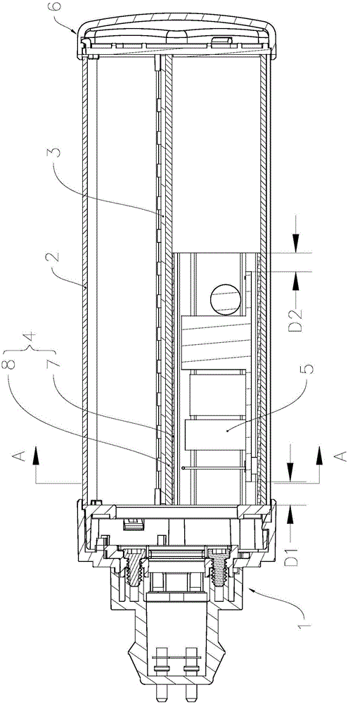
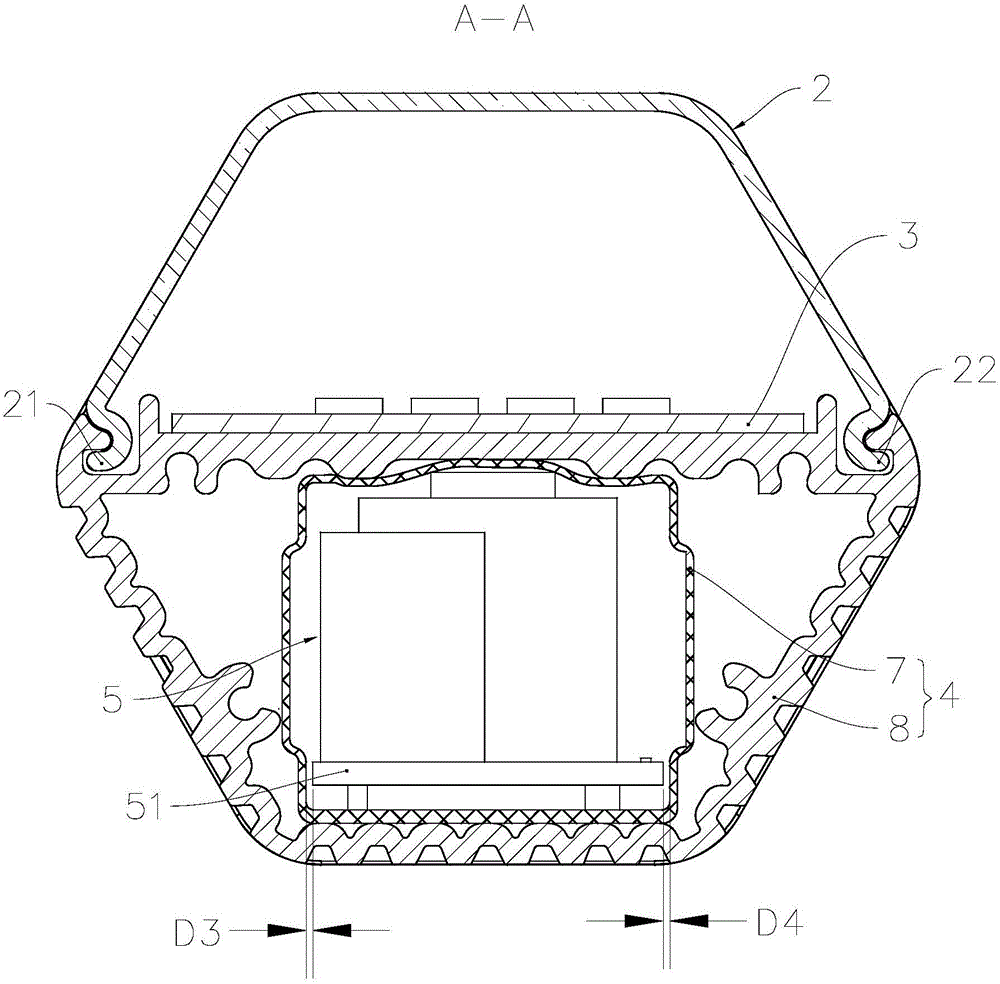
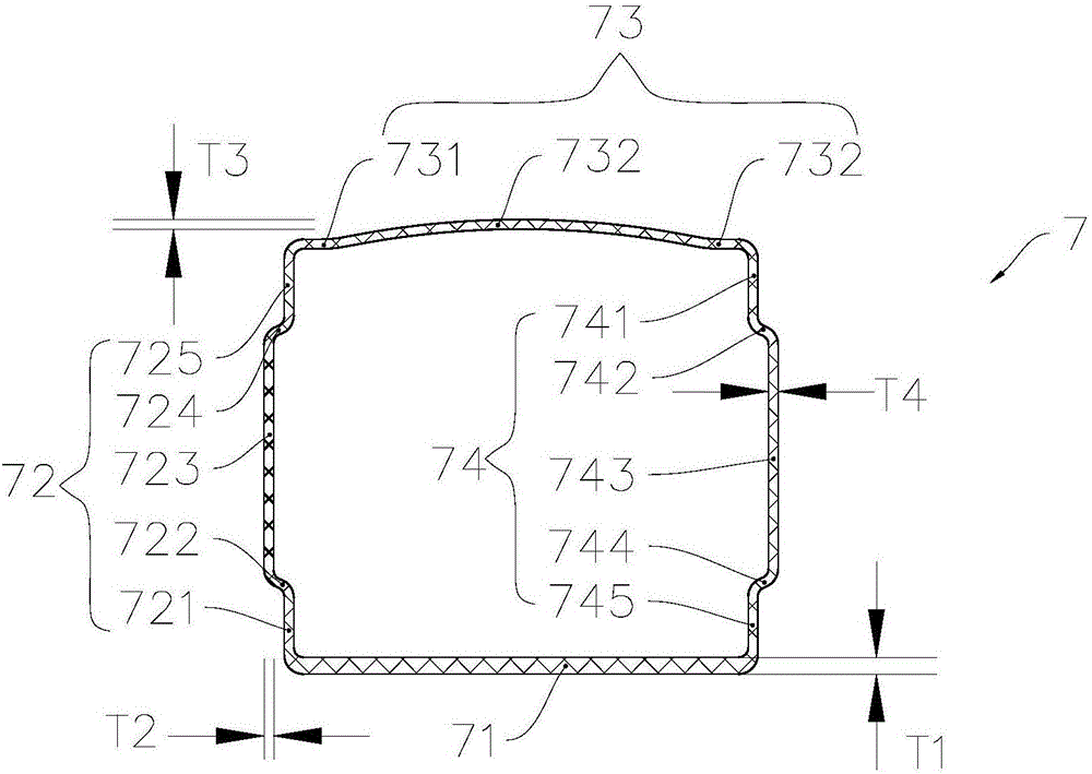
[0027] see figure 1 and figure 2 , The LED lamp has a lamp base 1, a lampshade 2, an aluminum substrate 3, a driver shell 4, a ...


PUM


Abstract

The invention relates to an LED lamp and a driver shell for the LED lamp and belongs to the field of illumination equipment. The driver shell comprises a plastic pipe and an outer shell with which the plastic pipe is sleeved. The plastic pipe is a first shell structure defined by the four walls in a sequential connection mode, and the outer shell is a second shell structure defined by the four walls in a sequential connection mode. During installation, a driver of the LED lamp abuts against the inner wall surface of the plastic pipe so as to position the driver in a close attachment mode, the outer wall surface of the plastic pipe abuts against the inner wall surface of the outer shell so as to position the plastic pipe in a close attachment mode, and the outer shell is fixedly connected with a lamp cap of the LED lamp, so that the driver is mechanically and electrically protected, the driver is conveniently installed in the LED lamp, and the using safety of the LED lamp is effectively improved. The driver shell can be widely applied to LED illumination.

Description

technical field [0001] The invention relates to the field of lighting equipment, in particular to an LED lamp and a driver shell for it. Background technique [0002] The patent document whose notification number is CN204785711U discloses a kind of LED lamp, which has a lamp cap and a cylindrical bulb fixedly connected with the lamp cap; A driver electrically connected to the pole is installed in the lamp holder. [0003] During the working process, in order to ensure that the driver can provide the required stable voltage for the normal operation of the LED, the driver needs to be protected electrically and mechanically. The commonly used protection methods are: (1) Wrap the PET insulating material outside the driver. The protection method is not only complicated in process, but also the welding feet of the components on the driver PCB board are easy to pierce the insulating layer, resulting in leakage or failure to meet the high-voltage resistance requirements; In this p...

Claims


Application Information

Patent Timeline
IPC IPC(8): F21V23/00F21V19/00F21V17/10F21V17/16F21Y115/10
CPCF21V17/10F21V17/164F21V19/001F21V23/003
Inventor 赵国松秦凤云
Owner CHENHUI GUANGBAO TECH CO LTD
Learn More