Electronic device and power converting unit thereof

A technology of electronic devices and drive shafts, applied in printing and other directions, can solve the problems of gear and rack surface impact, tooth surface damage, noise, etc.

Inactive Publication Date: 2009-03-04
QISDA CORP
View PDF0 Cites 0 Cited by
  • Summary
  • Abstract
  • Description
  • Claims
  • Application Information

AI Technical Summary

Problems solved by technology

[0007] When the system is restarted after a power failure, if the cleaning inkjet head mechanism 102 has moved to the initial position and the motor is still running, the transmission shaft continues to drive the gear 101 of the power conversion unit to rotate, causing the gear and the rack surface to interact with each other. Impact, destroy tooth flanks and generate noise

Method used


Image

  • Electronic device and power converting unit thereof
  • Electronic device and power converting unit thereof
  • Electronic device and power converting unit thereof

Examples


Embodiment Construction

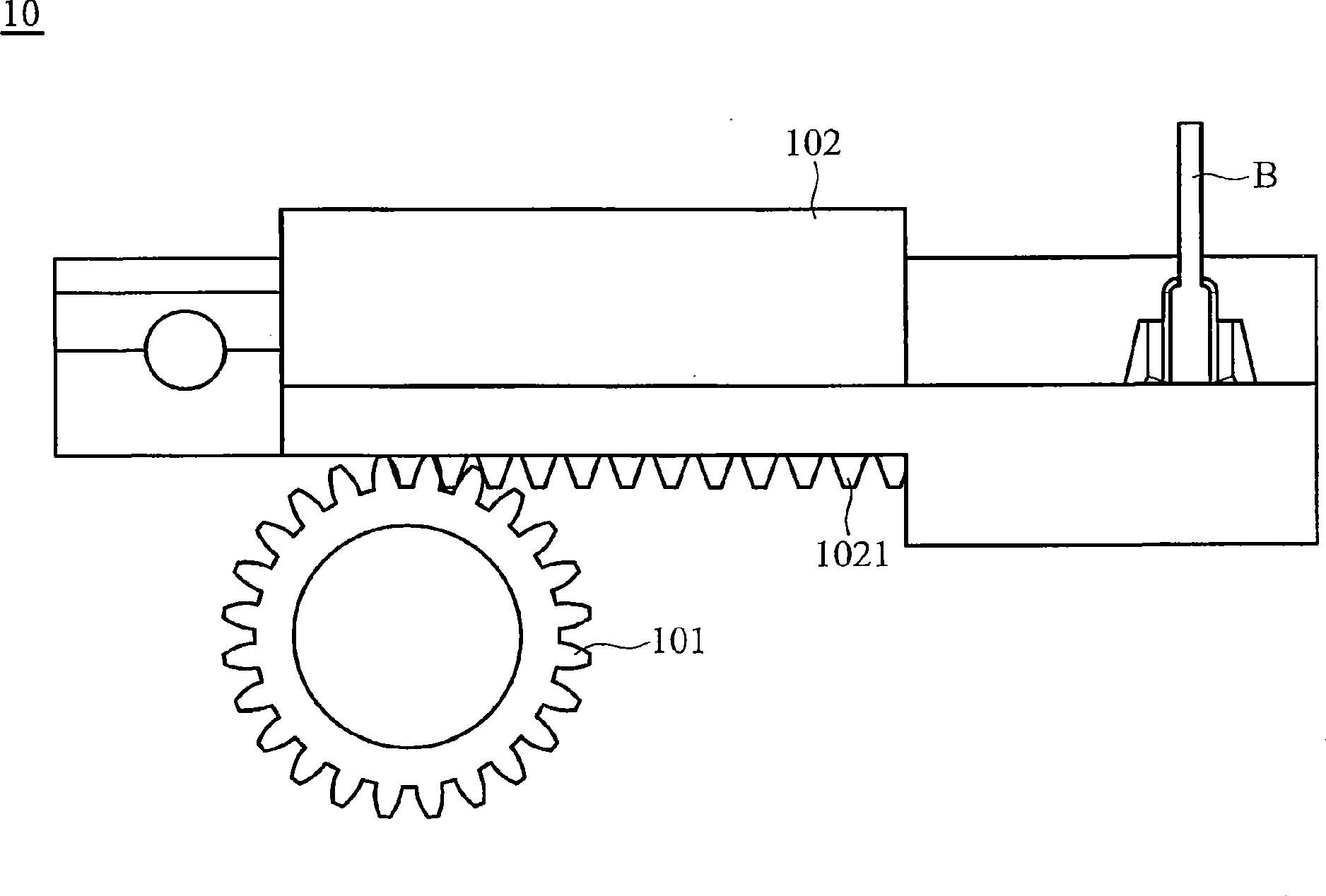
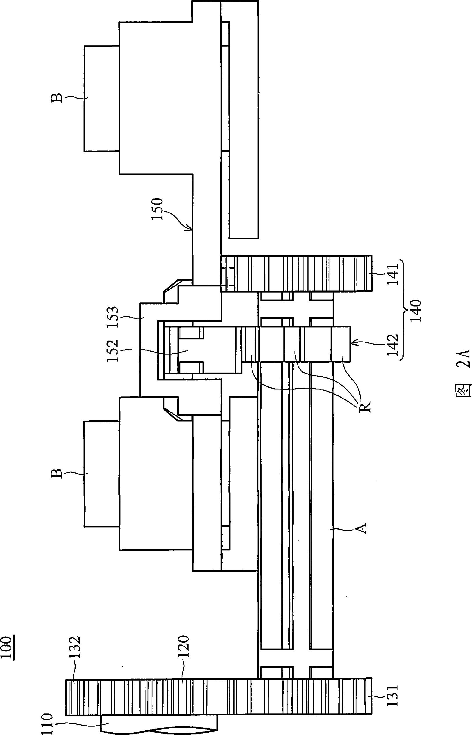
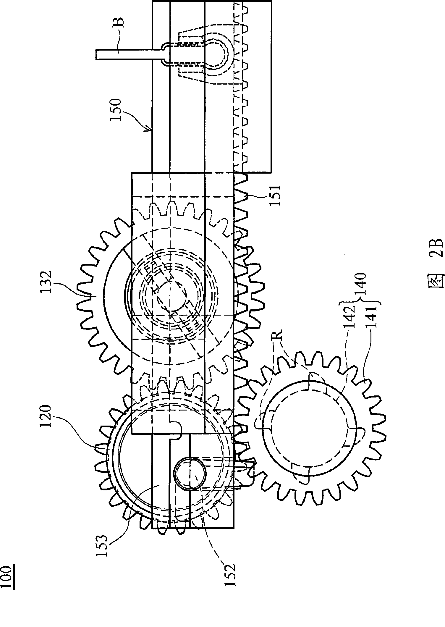
[0036] Referring to Fig. 2A and Fig. 2B, the electronic device 100 of the present invention is a printer, a fax machine, a photocopier or a multifunctional business machine, including a paper feeding mechanism, a cleaning inkjet head mechanism, a power conversion unit and a power device .

[0037] The power conversion unit includes a transmission shaft 110, a driving wheel 120, a first driven wheel 131 and a second driven wheel 132, the transmission shaft 110 is electrically connected with a power device to provide the power for the transmission shaft 110 to rotate, the transmission shaft 110 Connected with the driving wheel 120 to drive the driving wheel to rotate, the first driven wheel 131 and the second driven wheel 132 mesh with the driving wheel respectively. If the position of the wheel train is changed, the first driven wheel 131 can be selectively switched to be connected with the cleaning inkjet head mechanism (as shown in FIG. The driving wheel 132 can be selective...


PUM


Abstract

The invention discloses an electronic device and a power converting unit thereof. The power converting unit comprises a driving shaft, a rotating part and a moving part. The rotating part is connected with the driving shaft and comprises a first tooth part and a second tooth part. The moving part comprises a gear rack, a lifting arm and a stopping part, wherein the gear rack is used for being meshed with the first tooth part. The driving shaft drives the rotating part to rotate toward a first direction so that the first tooth part can be separated from the gear rack, and the second tooth part pushes the lifting arm to rotate toward a second direction. When the driving shaft drives the rotating part to rotate toward the second direction, the second tooth part pushes the lifting arm to rotate to the stopping part toward the first direction, the stopping part limits the rotating movement of the lifting arm, so that the lifting arm can move toward a third direction.

Description

technical field [0001] The present invention relates to an electronic device and its power conversion unit, in particular to an electronic device which utilizes an intermittent mechanism in the power conversion unit to improve the problem of mutual collision between gears and racks in the electronic device. Background technique [0002] In the printer, the power source conversion between the paper feeding mechanism and the cleaning inkjet head mechanism is to use the change of the gear position in the power conversion unit to switch the power, so that the power is output to the paper feeding mechanism or the cleaning inkjet head mechanism. [0003] When the gear of the power conversion unit is rotated to mesh with the gear of the paper feeding mechanism, the drive shaft drives the paper feeding mechanism to perform paper feeding. When the gear of the power conversion unit is rotated to mesh with the gear of the cleaning inkjet head mechanism, The drive shaft drives the mecha...

Claims


Application Information

Patent Timeline
Patent Type & Authority Applications(China)
IPC IPC(8): B41J23/02B41J2/165
Inventor 黄国风
Owner QISDA CORP
Why Eureka
Try Eureka