Centrifugal fan

A centrifugal fan and fan blade technology, used in non-variable volume pumps, non-displacement pumps, components of pumping devices for elastic fluids, etc., can solve problems such as high fan blade frequency peaks and reduce convexity Output ratio peak, improve gradient change, avoid the effect of fan blade frequency peak

Active Publication Date: 2013-05-22
DELTA ELECTRONICS INC
View PDF0 Cites 0 Cited by
  • Summary
  • Abstract
  • Description
  • Claims
  • Application Information

AI Technical Summary

Problems solved by technology

Therefore, although the setting of the throat T1 can avoid the occurrence of air backflow in the accommodating portion 121, the rapid change of pressure will occur due to the continuous impact of the air flow on the throat T1, which will cause the existing centrifugal fan 1 to generate relatively high pressure. The high peak frequency P2 of the fan blade and the problem of the protrusion ratio peak P1

Method used


Image

  • Centrifugal fan
  • Centrifugal fan
  • Centrifugal fan

Examples


Embodiment Construction

[0038] Hereinafter, the centrifugal fan according to the present invention will be described with reference to related drawings.

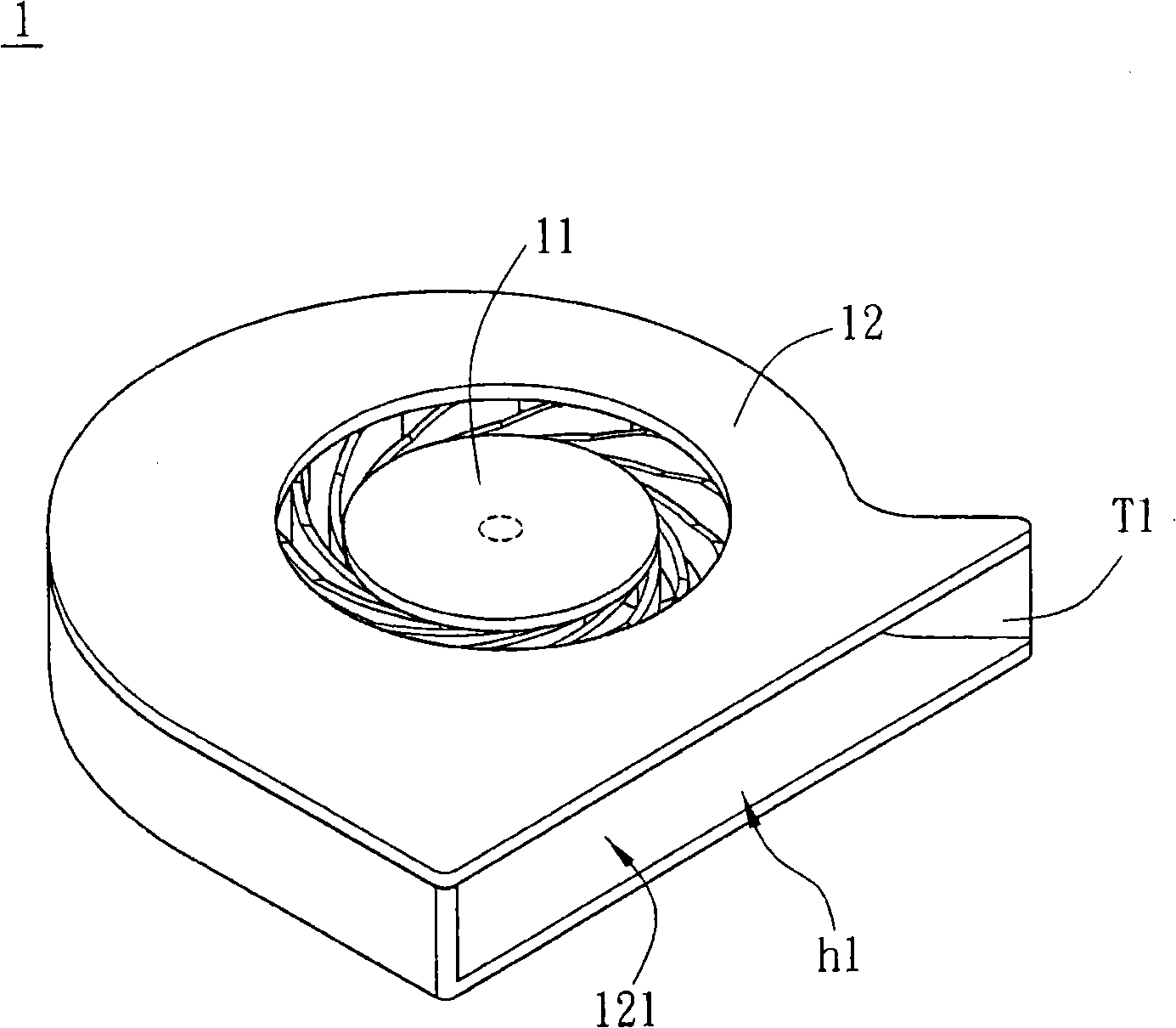
[0039] Please refer to Figure 3A As shown, the centrifugal fan 2 according to the first embodiment of the present invention includes a blade body 21 and a casing 22 .

[0040] The blade body 21 has an axis 211 . The casing 22 has an accommodating portion 221 , an axis fixed point 222 , a throat T2 and a recess 23 . In addition, the housing 22 further has a first sub-housing 223 , a second sub-housing 224 and an air outlet H1 . The first sub-housing 223 has a wall 223a, a bottom 223b and an air inlet H2, the wall 223a is disposed along the bottom 223b, and the second sub-housing 224 has an air inlet H3.

[0041] The blade body 21 is disposed in the accommodating portion 221 with the axis 211 corresponding to the axis fixed point 222 . Also, please refer to Figure 3B As shown, it is a top view of the first housing 223, if the first sub-housing...


PUM


Abstract

The present invention discloses a centrifugal fan, which comprises a blade body and a shell. The shell is provided with a containing part, a throat part and a concave part; wherein, the blade body is arranged in the containing part; a first axial line and a second axial line, which are vertical to each other at the central point of the shell, divide the shell into four areas; and the throat part and the concave part are positioned in a first area.

Description

technical field [0001] The invention relates to a fan, in particular to a centrifugal fan. Background technique [0002] With the development of electrical and electronic products, the demand for heat dissipation has also increased relatively, so heat dissipation technology has also become one of the development priorities of computer technology. Because the fan has the advantages of low cost and mature technology, it is used as a heat dissipation device in the product. [0003] Please refer to figure 1 As shown, the conventional centrifugal fan 1 includes a blade body 11 and a casing 12 . The casing 12 has an accommodating portion 121 , and the blade body 11 is disposed in the accommodating portion 121 . In addition, the casing 12 further has an air outlet h1 and a throat T1 , wherein the throat T1 is adjacent to the air outlet h1 . The throat T1 is provided to prevent the airflow that should be discharged from the air outlet h1 from being brought back into the accommod...

Claims


Application Information

Patent Timeline
Patent Type & Authority Patents(China)
IPC IPC(8): F04D17/08F04D29/66F04D29/42
Inventor 林星晨
Owner DELTA ELECTRONICS INC
Why Eureka
Try Eureka