High temperature reactant recycling for PEM fuel cell humidification

a technology of reactant and pem fuel cell, which is applied in the direction of fuel cell, cell components, fuel cell grouping, etc., can solve the problems of inability to humidify inlet air above approximately 42% relative humidity, water transport plates providing significant difficulty, etc., to improve the humidification of reactant gases, increase parasitic power, and reduce the flow of oxidant reactant gas

Inactive Publication Date: 2006-06-27
AUDI AG
View PDF5 Cites 8 Cited by
  • Summary
  • Abstract
  • Description
  • Claims
  • Application Information

AI Technical Summary

Benefits of technology

[0008]Objects of the invention with respect to a fuel cell, include: improved humidification of reactant gases in a fuel cell stack; achieving substantially saturated inlet reactant gases relative to the cell temperatures at the inlets by means of recycled reactant gases; self-humidification of fuel cell reactant gases without increasing parasitic power; reduction of oxidant reactant gas flow field pressure drop; improved PEM fuel cell flow field and recycle configuration for optimal humidification at lowest parasitic power.
[0009]According to the present invention, a fuel cell stack in which each fuel cell has a multiple-pass oxidant reactant gas flow field utilizes oxidant reactant gas taken from a turnaround manifold remote from a coolant inlet between flow field passes as recycle reactant gas to provide humidity to the oxidant recycle inlet gas. The invention utilizes oxidant reactant gas taken from a point in the fuel cell flow fields where the temperature, and therefore the vapor pressure and dew point of water, is the highest, thereby to not only return more moisture to the inlet, but to do it with a favorable dew point temperature differential compared with cooler inlet fluid so as to ensure saturation of the oxidant inlet gas relative to the inlet temperature of the cell.
[0010]According further to the invention, the fuel reactant recycle gas is taken from an outlet of a fuel flow field that is disposed on the stack with respect to the fuel cells thereof so as to be remote from the coolant inlet of said fuel cells, whereby the temperature is higher, the vapor pressure is higher, the dew point is higher, and more water vapor is returned from the recycle fuel gas to the inlet fuel gas, and the favorable temperature differential between the cooler fuel inlet ensures saturation of the fuel inlet reactant gas with water relative to the cell temperature at the fuel inlet.

Problems solved by technology

However, porous plates filled with water provide significant difficulty when they are routinely subjected to subfreezing conditions, because of the need to drain components to prevent mechanical damage, and because of the time and energy required to melt ice during startup procedures.
This renders water transport plates less attractive for implementing fuel cells which are to be used for powering vehicles.
Although no oxygen-depleted air is utilized in this configuration, because the dew point temperature of the air exiting the manifold is below that of the air entering the inlet manifold, the inlet air cannot be humidified above approximately 42% relative humidity.
It has been found that 42% (for instance) relative humidity at the air inlet is insufficient to operate the fuel cell without providing liquid water to internally humidify reactants within the cell.

Method used


Image

  • High temperature reactant recycling for PEM fuel cell humidification
  • High temperature reactant recycling for PEM fuel cell humidification
  • High temperature reactant recycling for PEM fuel cell humidification

Examples


Embodiment Construction

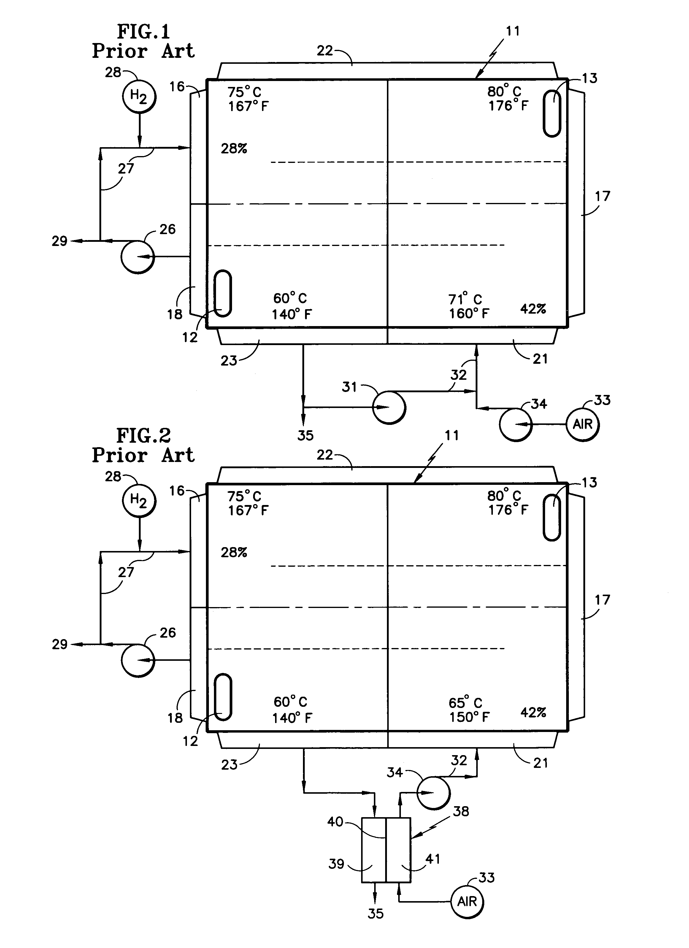
[0016]The reactant and coolant flow field configuration illustrated in FIGS. 1 and 2 is that which is disclosed and claimed in U.S. patent application Ser. No. 09 / 948,353, filed Sep. 7, 2001, now U.S. Pat. No. 6,572,995 which provides lower reactant gas exit temperatures, a more even cell temperature profile, a higher coolant exit temperature (which aids in removal of heat through a radiator) and permits cell operation with higher air utilization and lower coolant flow. However, it has been determined, in accordance with the invention, that the humidification of inlet fuel by means of fuel recycle is not optimal with that configuration.

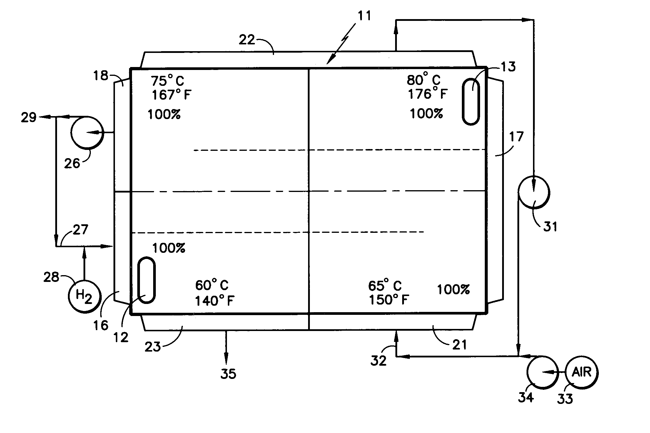
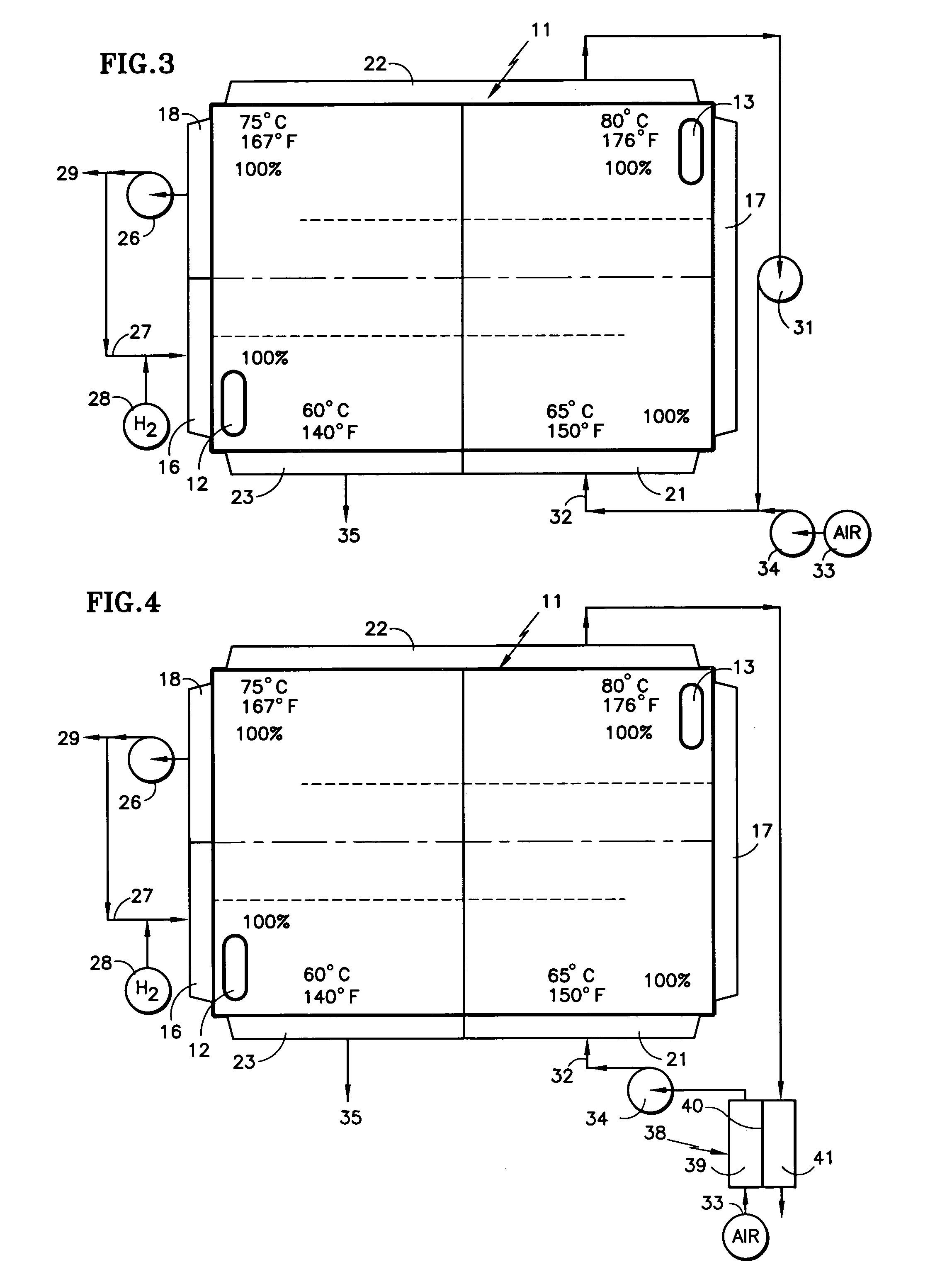
[0017]One of the features of the invention is improving the fuel side humidification as a consequence of a fuel recycle loop. Referring to FIG. 3, one form of the invention reverses the position of the fuel inlet manifold 16 and the fuel outlet manifold 18 so that the fuel outlet is remote from the coolant inlet and therefore the fuel at the outlet is...


PUM

PropertyMeasurementUnit
humidityaaaaaaaaaa
temperatureaaaaaaaaaa

Abstract

A fuel cell stack has an air inlet manifold (21), an air turnaround manifold (22) and an air exit manifold (23); a coolant inlet is adjacent said air exit manifold; a fuel inlet manifold (16) is connected through a turnaround manifold (17) to a fuel exit manifold (18) remote from said coolant inlet. Fuel recycle is taken from the fuel manifold where the temperature is warmer than it is near the coolant inlet; recycle air for humidifying and heating inlet air is taken from the air turnaround manifold (22), and may either be recycled air provided by a recycle pump (31), or it may utilize an enthalpy recovery device (38) to transfer heat and humidity from an outflow chamber (41) to an inflow chamber (39).

Description

TECHNICAL FIELD[0001]This invention relates to: recycling reactant gas exiting from one portion of a multi-pass reactant flow configuration remote from a coolant inlet of a proton exchange membrane (PEM) fuel cell, thereby to recycle moist reactant gas at substantially the highest temperature, and therefore substantially the highest dew point or vapor pressure, which the reactant reaches within the fuel cell, whereby to provide highly humidified recycled reactant for humidification of the incoming reactant; and to recycling fuel from a fuel flow field outlet remote from a coolant inlet, thereby to increase the temperature, and therefore the relative humidity, of the recycled fuel.BACKGROUND ART[0002]PEM fuel cells require humidification of both the oxidant reactant gas and the fuel reactant gas to prevent the membrane from drying out, thereby to avoid degradation of the membrane and of the fuel cell performance. One approach to humidifying the reactants is the use of water transport...

Claims


Application Information

Patent Timeline
Patent Type & Authority Patents(United States)
IPC IPC(8): H01M8/04H01M8/24
CPCH01M8/04119H01M8/2485H01M8/2415Y02E60/50H01M8/0267H01M8/2484H01M8/0258
Inventor BREAULT, RICHARD D.
Owner AUDI AG
Why Eureka
Try Eureka