Freeze capable compact fuel cell system with improved humidification and removal of excess water and trapped nitrogen

a fuel cell and compact technology, applied in the field of compact pem fuel cell systems, can solve the problems of affecting the efficiency of the fuel cell, the fuel cell design has faced challenges in operation, and the fuel cell operation is degraded, so as to facilitate the removal of excess water and nitrogen gas trapped in the fuel cell, and facilitate the improvement of the humidification of the fuel cell

Inactive Publication Date: 2007-09-06
GM GLOBAL TECH OPERATIONS LLC
View PDF20 Cites 10 Cited by
  • Summary
  • Abstract
  • Description
  • Claims
  • Application Information

AI Technical Summary

Benefits of technology

[0008] The present invention is directed to a freeze compatible compact fuel cell system to facilitate improved humidification of the fuel cell at start and during operation, as well as to facilitate removal of excess water and trapped nitrogen gas from the anode side of the fuel cell system.
[0009] The present invention is further directed to a freeze compatible fuel cell system with a merged, integrated anode outlet in fluid connection with a water separator which in turn is in fluid connection with the cathode inlet to facilitate improved humidification of the cathode inlet at start conditions.
[0010] The present invention is further directed to a design for a fuel cell system that has a short fluid connection between a merged anode outlet and a water separator and a short connection between the water separator and the cathode inlet to minimize freeze condition start difficulties.

Problems solved by technology

The entire assembly of catalysts and PEM is known in the art as the membrane electrode assembly (MEA) and is therefore quite expensive to make.
Among the conditions that degrade fuel cell operation are freeze start conditions, excess water, improper humidification, control of catalysts fouling and venting of excess gasses that migrate between the cathode and anode sides of the fuel cell stack.
In addition, residual water can accumulate in the anode side of the fuel cell stack and affect the efficiency of the fuel cell.
Moreover, fuel cell design has faced challenges in operation in dry or cold environments.
Specifically, proper humidification can be an issue in dry climates or dry starting conditions, as the cathode inlet and the PEM must be properly humidified on starting to ensure peak operation of the fuel cell stack.
In addition, excess water in the anode exhaust line or the anode side of the fuel cell stack can freeze in cold condition, making starting the fuel cell more difficult.

Method used


Image

  • Freeze capable compact fuel cell system with improved humidification and removal of excess water and trapped nitrogen
  • Freeze capable compact fuel cell system with improved humidification and removal of excess water and trapped nitrogen
  • Freeze capable compact fuel cell system with improved humidification and removal of excess water and trapped nitrogen

Examples


Embodiment Construction

)

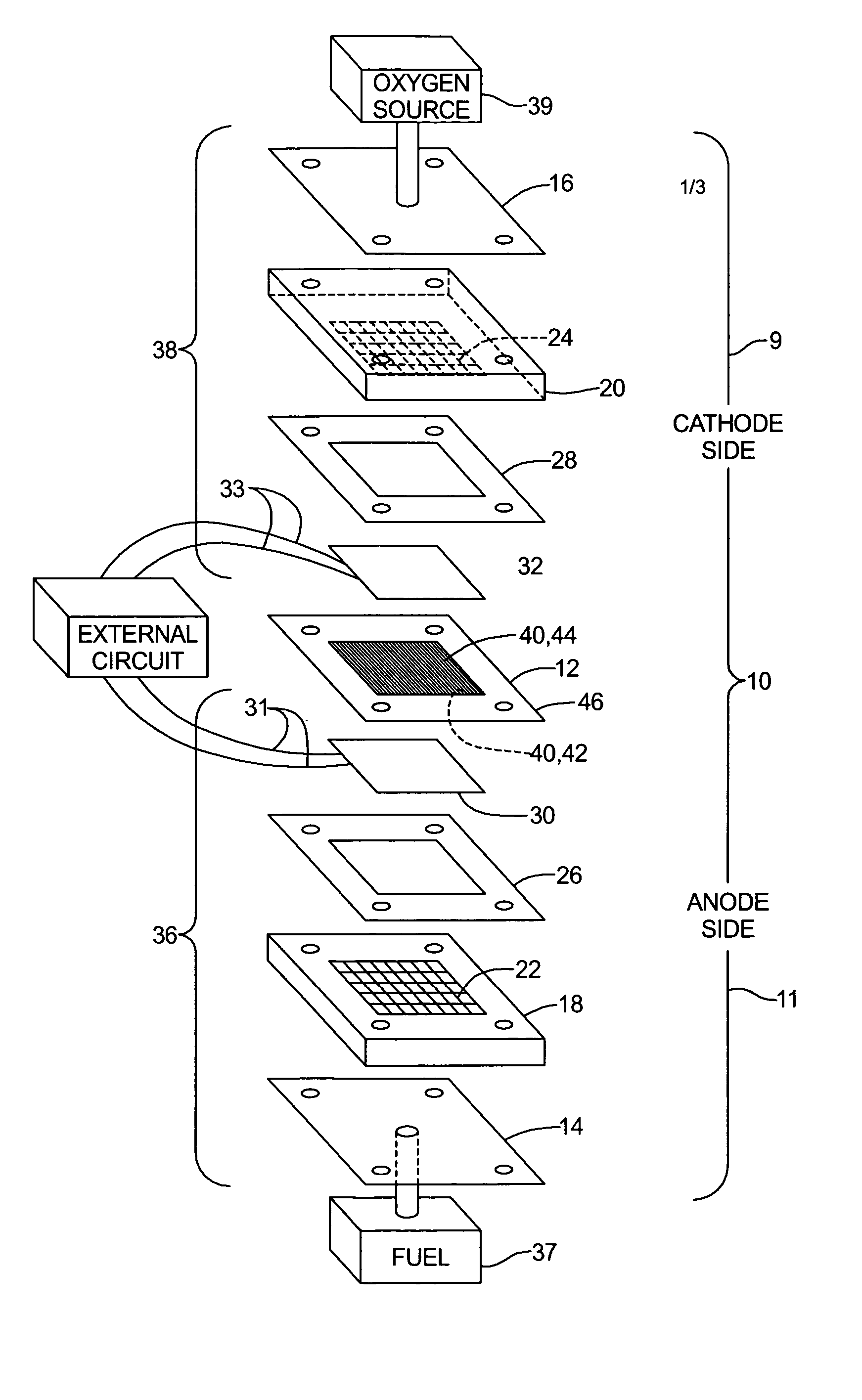
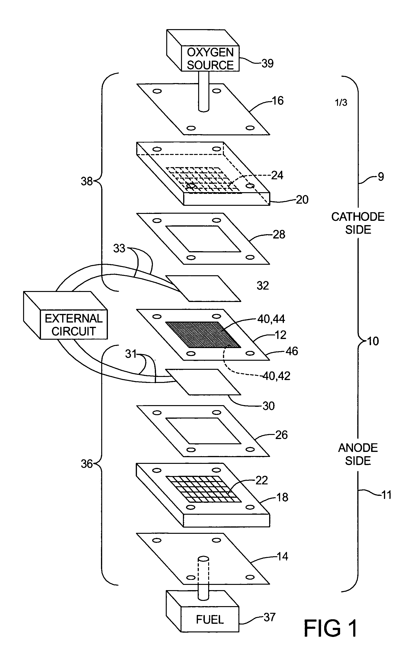
[0016] Turning now to the drawings wherein like numerals refer to like structures, and particularly to FIG. 1, there is shown a fuel cell 10 with a combination membrane electrolyte and electrode assembly (MEA) 12 incorporated therein is shown in pictorial unassembled form. Fuel cell 10 comprises endplates 14, 16, respectively, graphite blocks 18, 20, with openings 22, 24 to facilitate gas distribution, gaskets 26, 28, carbon cloth current collectors 30, 32, with respective connections 31, 33 and the membrane electrolyte and electrode assembly (MEA) 12. The two sets of graphite blocks, gaskets, and current collectors, namely 18, 26, 30 and 20, 28, 32 are referred to as perspective gas and current transport means 36, 38. Anode connection 31 and cathode connection 33 are used to interconnect with an external circuit and may include other fuel cells.

[0017] Fuel cell 10 includes gaseous reactants, one of which is fuel supplied from fuel source 37, which may be hydrogen or a hydrogen co...


PUM

PropertyMeasurementUnit
temperatureaaaaaaaaaa
operational temperatureaaaaaaaaaa
flow rateaaaaaaaaaa

Abstract

A freeze capable compact fuel cell system to facilitate improved humidification in dry operating conditions and improved freeze capability as well as to facilitate improved removal of excess water and trapped nitrogen gas from the fuel cell system. The fuel cell system is particularly adapted for integration into a small vehicle body.

Description

TECHNICAL FIELD [0001] This invention relates to compact PEM fuel cell systems that are freeze capable and provide for improved humidification as well as improved removal of excess water and trapped nitrogen gas. The compact PEM fuel cell systems of the present invention are especially suitable for integration into small vehicle bodies. BACKGROUND OF THE INVENTION [0002] Fuel Cells have been proposed as a power source for many applications. Proton Exchange Membrane (PEM) fuel cells exhibit attractive characteristics of high energy and low weight and are therefore very desirable for use as power plants in electric vehicles. PEM fuel cells include a thin, proton transmissive solid polymer membrane electrolyte having an anode on one of its faces and a cathode on the opposite face. The membrane in a PEM fuel cell is typically made from a poly sulfonic acid or poly[perfluorinated] sulfonic acid monomer that is polymerized into a copolymer. The PEM is sandwiched between a pair of electric...

Claims


Application Information

Patent Timeline
Patent Type & Authority Applications(United States)
IPC IPC(8): H01M8/02H01M8/10H01M8/24
CPCH01M8/04164H01M8/04231Y02E60/50H01M2008/1095H01M8/04253
Inventor KOENEKAMP, ANDREASESSINGER, REINERWINTER, FRANZ
Owner GM GLOBAL TECH OPERATIONS LLC
Why Eureka
Try Eureka