Air humidification for fuel cell applications

a technology of air humidification and fuel cell, which is applied in the direction of fuel cells, solid electrolyte fuel cells, cell components, etc., can solve the problems of increasing the cost and complexity of the system, the cathode side of the fuel cell cannot always be humidified, and the humidification control of the fuel cell stack cannot always be maintained, so as to reduce the temperature of the oxidant and increase the water transfer rate of the humidifier

Inactive Publication Date: 2006-06-22
GM GLOBAL TECH OPERATIONS LLC
View PDF5 Cites 11 Cited by
  • Summary
  • Abstract
  • Description
  • Claims
  • Application Information

AI Technical Summary

Benefits of technology

[0006] According to a preferred embodiment of the present invention, improved air humidification for fuel cell applications includes a fuel cell stack air humidification system which includes a fuel cell stack having a cathode inlet and a cathode outlet. The cathode inlet is operable to receive an oxidant into the fuel cell stack. A humidifier is operable to humidify the oxidant prior to delivery of the oxidant to the cathode inlet. An injection nozzle is also provided, wherein a volume of water substantially vaporized by the injection nozzle is operable to reduce a temperature of the oxidant and increase a water transfer rate of the humidifier.

Problems solved by technology

Adequate humidification control of the fuel cell stack cannot always be maintained, however.
During certain operating conditions the atmospheric air normally used for the oxidizing agent does not contain sufficient water volume and the cathode side of the fuel cells can therefore be inadequately humidified.
This additional process step increases the cost and complexity of the system.
These components also increase system cost and complexity.
However, if the humidity at the humidifier inlet drops below 100% RH the efficiency of the humidifier will drop significantly.
One solution to this problem is to increase the size of the humidifier, however this solution increases the component cost of the humidifier and can result in further configuration problems for the system.

Method used


Image

  • Air humidification for fuel cell applications
  • Air humidification for fuel cell applications
  • Air humidification for fuel cell applications

Examples


Embodiment Construction

[0016] The following description of the preferred embodiments is merely exemplary in nature and is in no way intended to limit the invention, its application, or uses.

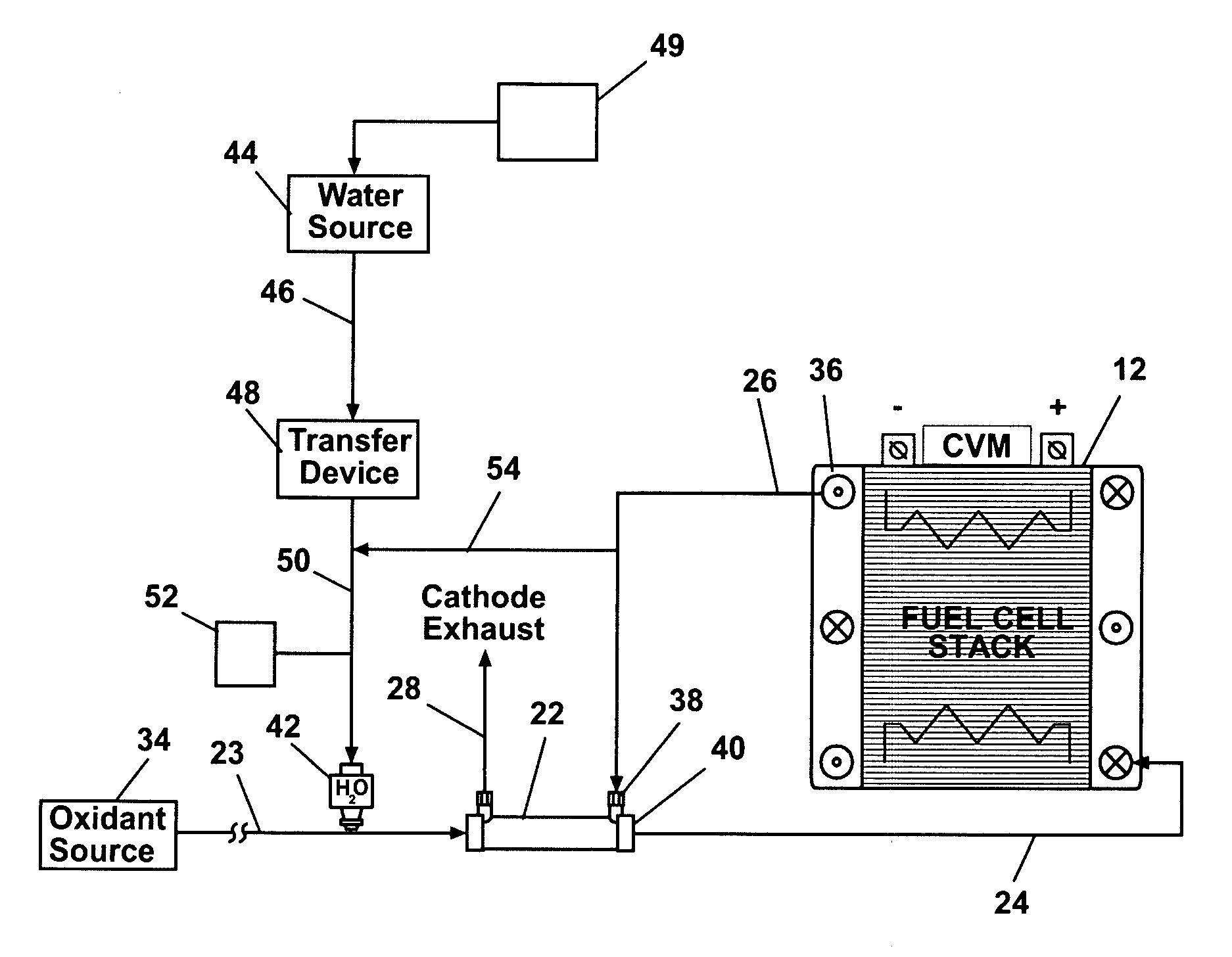
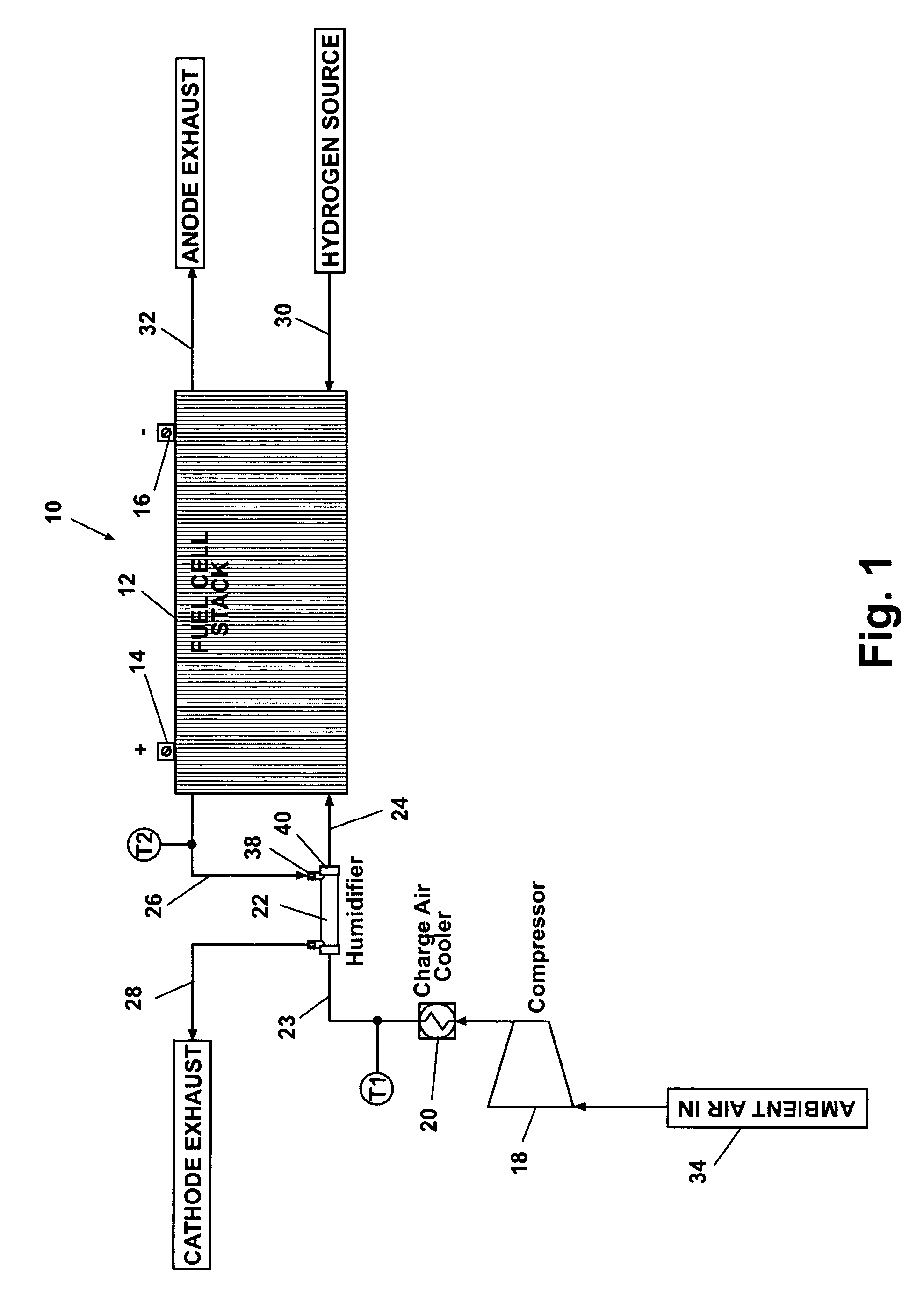
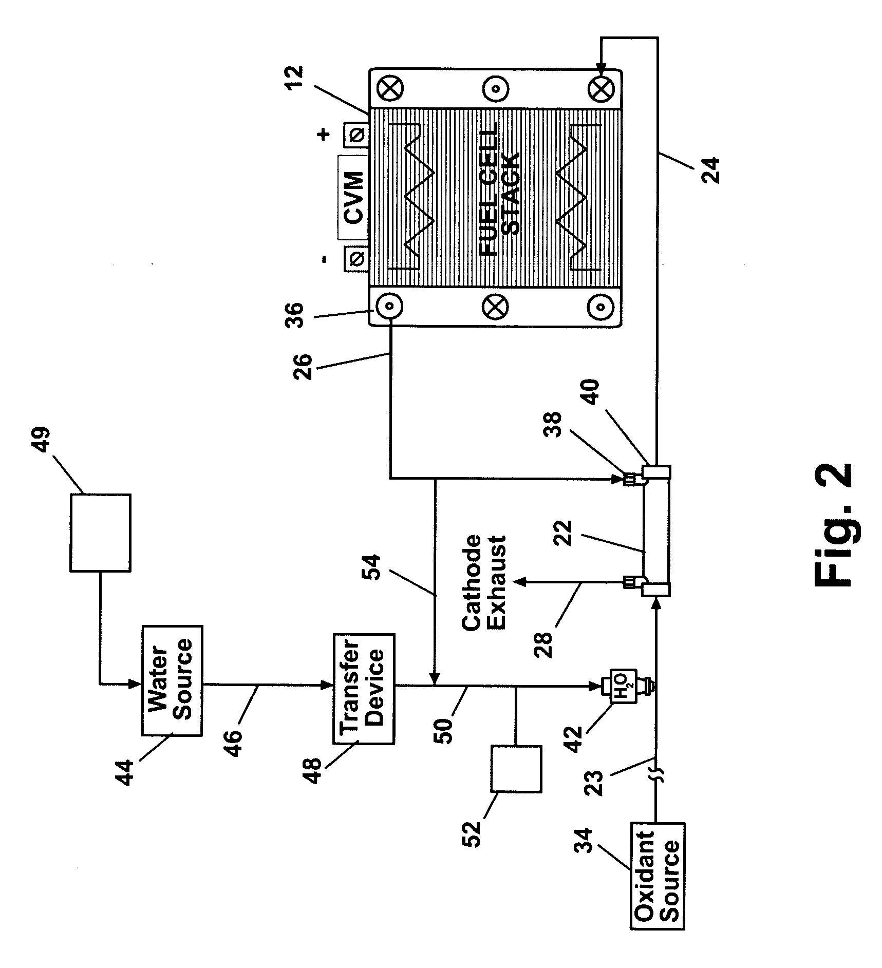
[0017] According to a preferred embodiment of the present invention and referring generally to FIG. 1, an air humidification system 10 includes a fuel cell stack 12 having electrical connections 14 and 16. Ambient air providing a source of oxygen to the cathode side of the cells of the fuel cell stack 12 is compressed using a compressor 18. Compressed air discharging from compressor 18 is subsequently cooled by a charge air cooler 20. The cooled air discharging from charge air cooler 20 is received in a humidifier 22 via a humidifier inlet line 23. The compressed and humidified air is discharged from humidifier 22 into the individual cathode sides of each cell of fuel cell stack 12 via a humidifier outlet line 24 that communicates with a cathode inlet manifold as is known in the art. A cathode air / water outlet line 26...


PUM

PropertyMeasurementUnit
RHaaaaaaaaaa
temperatureaaaaaaaaaa
RHaaaaaaaaaa

Abstract

A system and method for improving air humidification for fuel cell applications includes a fuel cell stack having a cathode inlet and a cathode outlet. The cathode inlet receives an oxidant. A humidifier humidifies the oxidant prior to delivery of the oxidant to the cathode inlet. An injection nozzle is provided, and a volume of water substantially vaporized by the injection nozzle reduces a temperature of the oxidant and increases a water transfer rate of the humidifier. The injection nozzle can be positioned either directly upstream of the humidifier in the oxidant inlet line or in a stack cathode outlet line which is directed into the humidifier.

Description

FIELD OF THE INVENTION [0001] The present invention relates in general to fuel cell humidification systems and more specifically to a system and method for use to control the cathode inlet humidity of a fuel cell stack. BACKGROUND OF THE INVENTION [0002] Fuel cell systems frequently include a plurality of fuel cells assembled together to form a fuel cell stack. Proton Exchange Membrane (PEM) type fuel cells normally include an anode, a cathode and a membrane separating the anode and cathode. Each of the anodes of the individual fuel cells are both electrically and fluidly connected together such that the plurality of anodes are commonly referred to as the anode side of the fuel cell stack. Similarly, each of the cathodes of the individual fuel cells are both electrically and fluidly connected together and commonly referred to as the cathode side of the fuel cell stack. The anode side of the fuel cell stack includes an inlet for a fuel and an outlet for the non-consumed fuel and for ...

Claims


Application Information

Patent Timeline
Patent Type & Authority Applications(United States)
IPC IPC(8): H01M8/04H01M8/10
CPCH01M8/04126H01M8/241H01M2004/8689H01M2008/1095Y02E60/50
Inventor GUNTHER, DETLEFKONIG, CHRISTIANRUHL, JOHN
Owner GM GLOBAL TECH OPERATIONS LLC
Why Eureka
Try Eureka