Mixed-flow device of ship diversion propelling system

A propulsion system and mixed-flow technology, which is applied to ship propulsion, propulsion components, rotary propellers, etc., can solve problems such as not being recycled or utilized, propulsion load reduction, and propulsion efficiency reduction

Inactive Publication Date: 2010-06-16
孙志伟
View PDF6 Cites 9 Cited by
  • Summary
  • Abstract
  • Description
  • Claims
  • Application Information

AI Technical Summary

Problems solved by technology

If these jets with higher energy directly enter the stern wake of the ship, they also have the same problems as the jets of the water jet propulsion system; if they enter the rear propeller or pump wheel, then this part of energy will not be obtained. Recycling or utilization, and will lead to a decrease in propulsion load and a reduction in propulsion efficiency

Method used


Image

  • Mixed-flow device of ship diversion propelling system
  • Mixed-flow device of ship diversion propelling system
  • Mixed-flow device of ship diversion propelling system

Examples


Embodiment 1

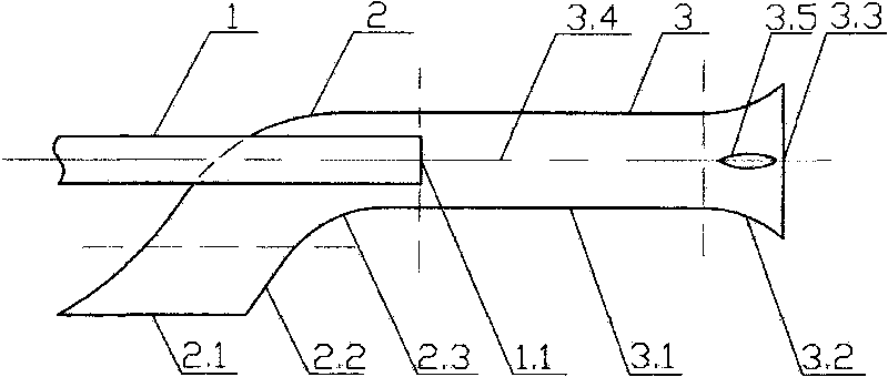
[0030] Such as figure 1As shown, the mixed flow device at the rear of the water jet propulsion system is mainly composed of three parts: the jet pipe 1, the follower pipe 2 and the mixed flow pipe 3. This is equivalent to upgrading the water jet pipe of the water jet propulsion system to a mixed flow device. Wherein, the jet pipe 1 of this mixing device is just equivalent to the original spray pipe; the follower pipe 2 includes the bell mouth 2.2 of the follower pipe and the elbow 2.3 of the follower pipe; the mixed flow pipe 3 includes the mixed flow part 3.1 and The bell mouth 3.2 of the mixed flow tube has a split fluid 3.5 and its support in the bell mouth 3.2 of the mixed flow tube.

[0031] At the moment when the propulsion pump of the water jet propulsion system starts forward, the positive pressure difference is transmitted from the propulsion pump to the mixed flow chamber 3.4 through the jet pipe 1, and the water in the mixed flow chamber 3.4 flows to the outlet 3.3...

Embodiment 2

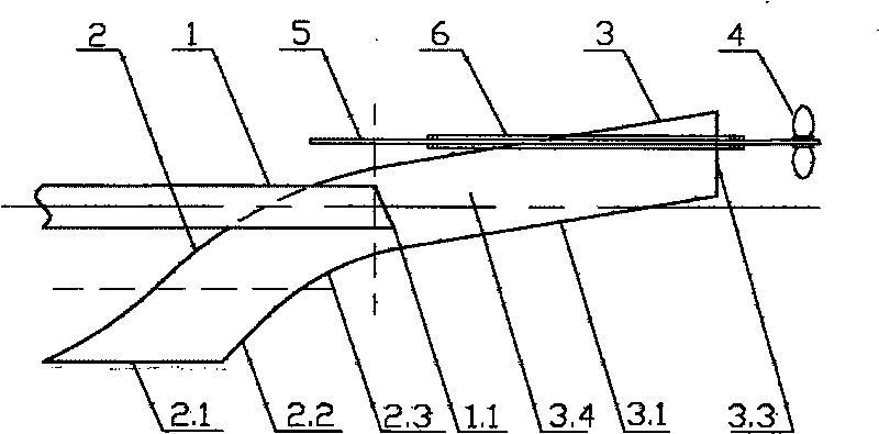
[0034] Such as figure 2 As shown, the mixing device in front of the propeller or the pump wheel is mainly composed of three parts: the jet tube 1, the follower tube 2 and the mixing tube 3. Among them, the jet pipe 1 is equivalent to the original water spray pipe; the follower pipe 2 includes the bell mouth 2.2 of the follower pipe and the bend pipe 2.3 of the follower pipe; the mixed flow pipe 3 is mainly the mixed flow part 3.1 of the mixed flow pipe. The mixed flow tube 3 deflects in the direction opposite to the inlet 2.1 of the follower tube relative to the centerline of the jet tube 1, and its deflection angle is smaller than the angle of the flow direction of the follower entering the mixed flow tube 3 relative to the centerline of the jet tube 1. The end face of the nozzle 1.1 of the jet tube is deflected in the deflection direction of the mixing tube 3 .

[0035] There is a propeller or a pump wheel 4 behind the outlet 3.3 of the mixing tube. The transmission shaft...


PUM


Abstract

The invention discloses a mixed-flow device of a ship diversion propelling system, aiming at solving the problem of jet flow of the ship diversion propelling system. The mixed-flow device mainly consists of a jet pipe, a wake flow pipe and a mixed-flow pipe, wherein a nozzle of the jet pipe and an outlet of the wake flow pipe are communicated with the mixed-flow device; an inlet of the wake flow pipe is arranged at the lateral side of the jet pipe; the cross section of the jet pipe is less than that of the mixed-flow pipe; and jet flow and wake flow are acted and mixed together in a mixed-flow cavity. By comparing water flow at the outlet of the mixed-flow pipe with the water flow at the nozzle of the jet pipe, the invention reduces the speed and increases the flow so as to improve the stern flow field of the ship, reduce the wave making resistance of the stern, or improve the flow field of a propeller or a pump impeller, improve the propelling efficiency and reduce damage of vacuole and water attach. The induced velocity generated by the water flow at the outer side of the inlet of the wake flow pipe and the induced pressure converted thereby can be further used for improving the stern flow field of the ship and reducing the wave making resistance of the stern.

Description

technical field [0001] The invention belongs to the technical field of ship propulsion, and specifically relates to a method for solving the jet problem in ship propulsion technology, especially diversion propulsion technology, to improve the flow field of the ship and its propulsion system, thereby reducing the wave-making resistance of the ship And a mixed flow device to improve the propulsion efficiency of the ship. Background technique [0002] Ships are used in a wide range of applications, such as transportation, fishing, engineering, ocean development, and military affairs. This requires a wide variety of high-performance ships. The main performance of a ship, such as speed, maneuverability, seakeeping and economy, is mainly affected and restricted by the ship type and propulsion system. Under the existing technical conditions, the high performance of ships mainly refers to rapidity, and often at the cost of sacrificing economy. [0003] The existing ship propulsio...

Claims


Application Information

Patent Timeline
Patent Type & Authority Applications(China)
IPC IPC(8): B63H11/02
CPCB63H5/16B63B1/40B63H11/02B63H1/28Y02T70/125Y02T70/10
Inventor 孙志伟
Owner 孙志伟
Why Eureka
Try Eureka