Hull having minimized wave-making characteristics

a wave-making characteristic and hull technology, applied in the field of vessels, to achieve the effect of reducing wave drag, improving performance, and minimizing bow wave-making

Inactive Publication Date: 2005-10-25
CROSS BAY IP
View PDF2 Cites 4 Cited by
  • Summary
  • Abstract
  • Description
  • Claims
  • Application Information

AI Technical Summary

Benefits of technology

[0010]The '595 application provides a hull form that operates in the speed ranges where both planing and wave-making affect hull resistance with a configuration which reduces wave drag and improves performance in very fast and ultra-fast speed ranges. The hull form is constructed so that there are variations in the distribution of immersed cross-sectional area that affect wave-making resistance. The specific distribution of immersed cross-sectional area minimizes bow wave-making and optimizes the closing wake. The bow wave impedes forward motion of a hull form. The stern closing wake pushes the hull forward and enhances the forward motion. The bow sections are designed so that they have a “hollow” entrance configuration, which decreases the effort to spread the water and in turn diminishes the wave-making as the hull pushes through the water. The stern sections are designed to be of such a configuration that as the water spread by the bow now must close in around the stern of the hull, the wave height is increased so that the closing wake exerts a forward thrust on the hull. The stern wave caused by hull shape, is augmented or made higher, so that the bow sections reduce the wake height and the stern sections increase the wake height. The keel line at the bow has a slight upward slope to allow for thinner bow sections and create hollow waterlines forward. The aft keel line has a long slope up and aft to allow for fuller and more nearly rectangular stern sections and create convex waterlines which form a slightly rounded side in the after body. Curving the afterbody section in towards the hull centerline increases the advantage of the closing thrust created by the stern wake. The sections aft of midships are all designed as low deadrise, hard chine sections where the dynamic lift surface for planing is optimized. While these bow and stern designs complement each other as described above, a hull implementing just the novel bow or stern design may be formed and offer the respective advantages provided by the bow or stern design. The bow and stern portions of the vessel (i.e., the entrance and run, respectively) can be defined as discrete segments, each having its own properties and advantages.
[0011]A semi-displacement hull in accordance with the '595 application significantly reduces the wave-making drag of the hull at the high speed range (TQ=2.0) of vessel operation thereby allowing the vessel to reach ultra-high speeds where planing characteristics dominate hull behavior. The semi-displacement hull also includes an aft body that is developed for planing. The semi-displacement hull also may include derivative hull configurations, from a set of formulas, where hull coefficients may be varied. The invention also provides a multi-hulled high speed or ultra-high speed vessel using the semi-displacement hull.
[0023]In this way, the invention provides an ocean-going cargo vessel capable of high speeds where a combination of low wave drag and planing lift cause a reduction in powering requirements over other conventional hull forms. The invention also provides a vessel which has a suitably large block coefficient providing sufficient cargo capacity to create suitable revenues to justify the vessel's use.
[0024]According to the invention, low hull resistance and reduced wave-making are attained by a specific distribution of immersed cross-sectional areas, related to a specific design waterline draft, that creates a volume with concave surfaces in the forebody and convex surfaces in the afterbody and a specific alignment of the keel in reference to the baseline. The length of the forebody, or run of the entrance, is about 0.6 L from the forward point at the stern of the hull. The bottom surfaces of the hull are narrow with a high deadrise in the forebody and decrease as the entrance approaches the section of maximum cross-sectional area about 0.6 L from the stern and then continue on to the stern with a relatively low deadrise. The planing surfaces must be broad and relatively flat in order to optimize the lift provided by bottom pressures. This characteristic of broad, flat sections increases the wave-making and is often at odds in very fast and ultra-fast hull designs. According to the invention, the wave-making of the broad planing areas of the hull are used to add a forward component of thrust due to the closing wake generated by these broad planing areas.
[0025]A natural extension of hull area distribution is to use form modifiers, which vary the area distribution of existing hulls to conform to the optimized distribution, as proposed by this invention. For example, appendages to the side of the hull or sponson-like additions acting as form modifiers may be positioned where they are always immersed in a semi-displacement hull and operate effectively to reduce wave-making.
[0027]The foregoing concepts, parameters and equations may further be applied to a full displacement hull, such as a tanker hull. Applying these concepts to a full displacement hull improves entrance and minimizes wave-making characteristics. In one embodiment, sponsons may be used to create the waterline offsets. This concept allows a forward portion of a vessel to be fitted to an existing engine room, or to improve the overall efficiency of the existing vessel. For instance, bow sections can be modified by sponsons to create the correct ratios of Bn / B as specified in this invention.

Problems solved by technology

This minimization results in straight sides, and does not create compound curves for the side shell.

Method used


Image

  • Hull having minimized wave-making characteristics
  • Hull having minimized wave-making characteristics
  • Hull having minimized wave-making characteristics

Examples


Embodiment Construction

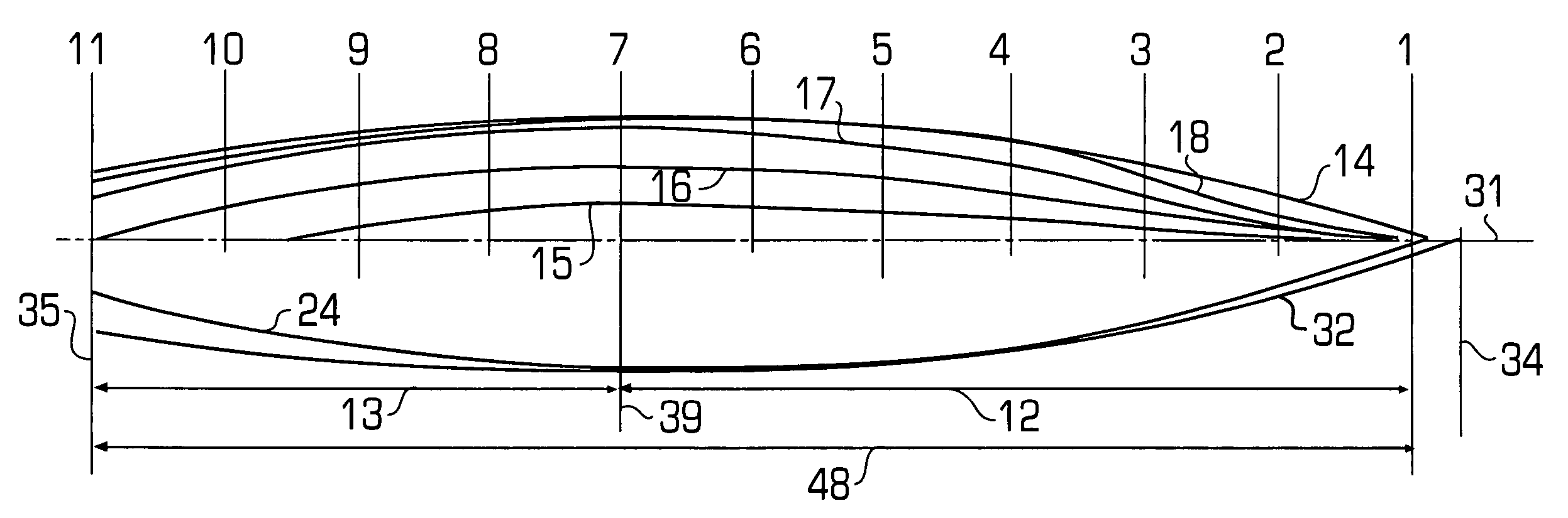
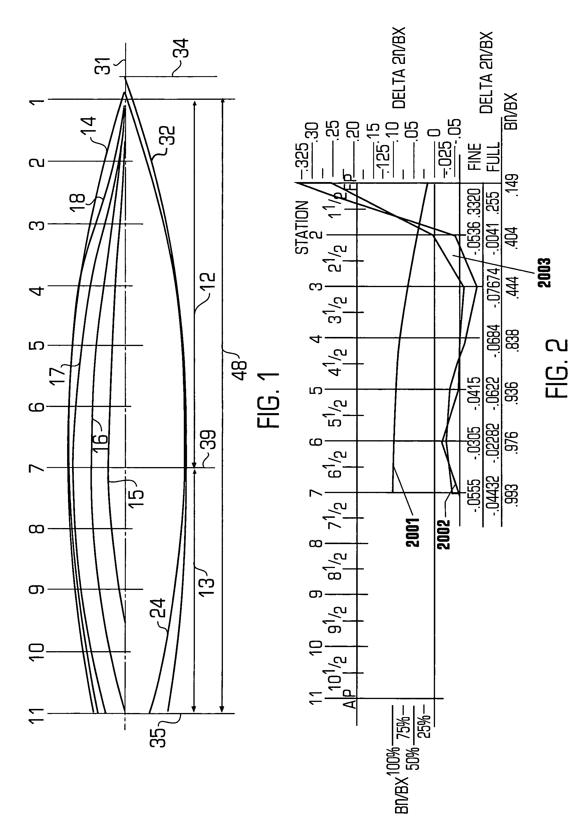
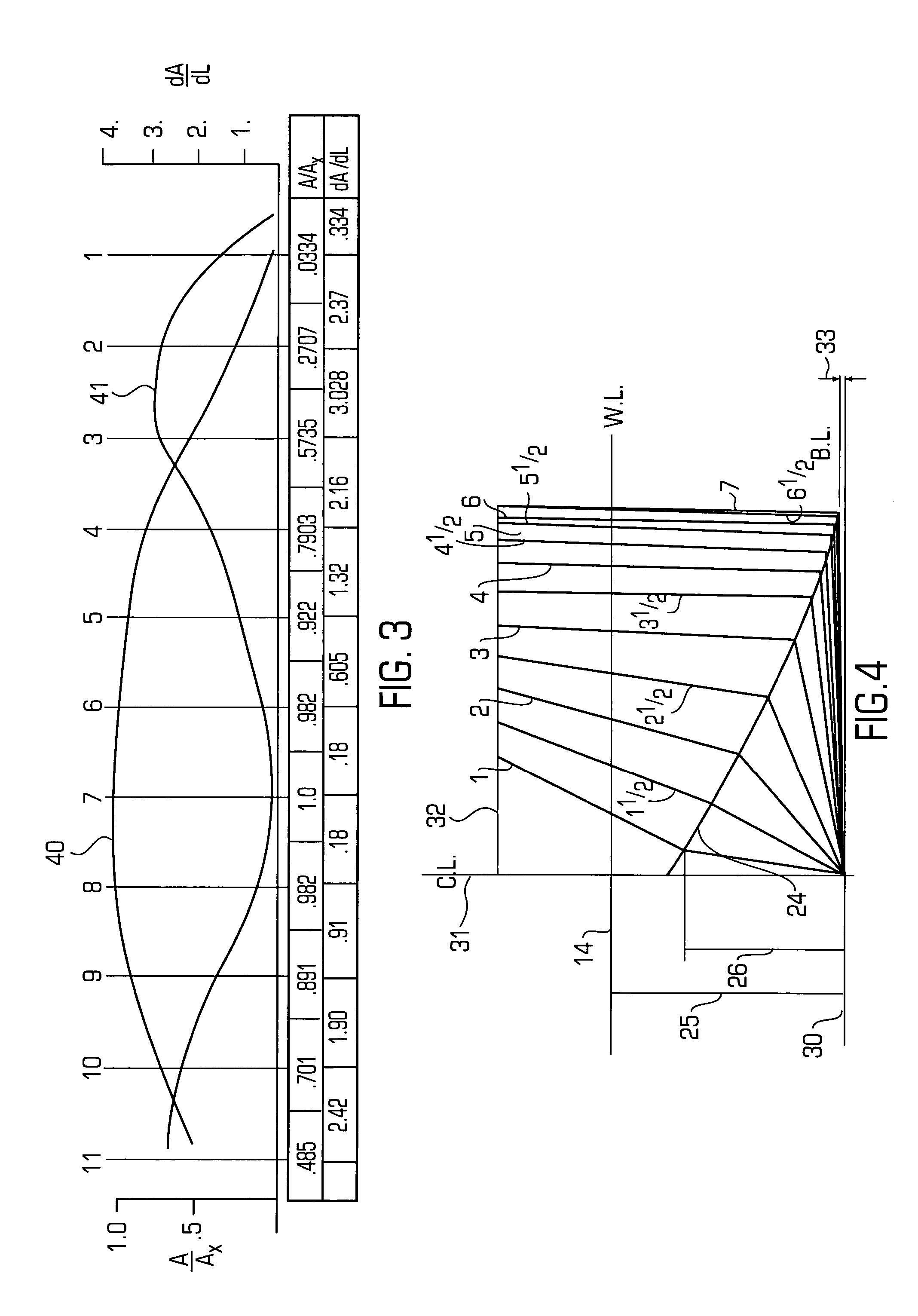
[0052]The present discussion applies the principles disclosed in the '595 application, which is fully and completely incorporated herein by reference, to a full displacement hull. While the following discussion relates to a full displacement type hull, such as a tanker hull, it should be appreciated that the invention is applicable to both full displacement hulls and semi-displacement hulls, and that the teachings of the invention may be applied to design hulls that are being manufactured or to modify existing hulls. Furthermore, although the invention provides design concepts for both the forebody (e.g., bow portion) and afterbody (e.g., stern portion) of a hull, the advantages provided by the bow and stern offset designs are not dependent upon each other to create separation and closing effects. Thus, the present invention may be used to design or modify an improved hull that implements either the bow or stern offset design taught herein, or that implements both the bow and stern ...


PUM


Abstract

A hull form is presented and dimensioned where the design parameters consist principally of the breadth of the hull at the waterline, taken at specific equal intervals along the length of the waterline. The waterline reference is that at which the vessel is intended to float in the loaded condition. The waterline breadths describe the entrance or bow of the vessel. The closing run or stem of the vessel is not specifically delineated as a feature of the entrance or related to it. The invention defines two parts of the vessel, the entrance and the run, as discrete segments, each having its own properties and advantages. The entrance of the vessel is concerned with wave-making and the creating of a wave front that opposes vessel forward motion. The invention describes a method of optimizing the entrance of a vessel, and modifying the entrance of an existing vessel to minimize wave-making characteristics.

Description

CROSS REFERENCE TO RELATED APPLICATIONS[0001]This application is a continuation-in-part of U.S. patent application Ser. No. 09 / 979,595, filed on Mar. 4, 2002 now U.S Pat. No. 6,668,734, which is fully and completely incorporated by reference, and which claims priority and is a 371 of PCT International Application Serial Number PCT / US00 / 13927 filed on May 18, 2000 claiming priority from an earlier U.S. Provisional Patent Application Ser. No. 60 / 134,743 filed May 18, 1999, both of which are incorporated by reference.FIELD OF THE INVENTION[0002]This invention relates generally to vessels. More specifically, the invention relates to a vessel having a hull form that is configured to reduce the wave-making characteristics of the vessel operating as a full displacement hull, where planing effects do not exist.BACKGROUND OF THE INVENTION[0003]It is desirable to reduce wave-making characteristics in the hulls of water vessels, such as full displacement hulls. The vessels which can benefit fr...

Claims


Application Information

Patent Timeline
Patent Type & Authority Patents(United States)
IPC IPC(8): B63B1/16B63B1/18B63B1/00B63B1/12
CPCB63B1/121B63B1/18B63B2001/204B63B1/06B63B1/40B63B2001/066B63B2001/201Y02T70/10
Inventor REYNOLDS, ZACHARY M.
Owner CROSS BAY IP
Why Eureka
Try Eureka