
Variable wing leading edge combining subsonic aerodynamic performance and supersonic aerodynamic performance

A technology for leading edge and aerodynamic performance of wings, applied in supersonic aircraft, wings, motor vehicles, etc., can solve the problems of decreased aerodynamic efficiency, low lift-to-drag ratio, increased fuel consumption, etc., to reduce the use cost, High lift-drag ratio, the effect of improving lift-drag ratio

Active Publication Date: 2018-11-06
BEIHANG UNIV
View PDF6 Cites 4 Cited by
  • Summary
  • Abstract
  • Description
  • Claims
  • Application Information

AI Technical Summary

Problems solved by technology

When the aircraft is flying at a subsonic speed, the airflow above the stagnation point on the surface of the sharp wing leading edge must move upward to bypass the sharp wing leading edge, and the sharp wing leading edge with an infinitely small radius of the wing leading edge will cause the air flow to The surface of the sharp wing leading edge separates to produce leading edge separation bubbles, and the leading edge separation bubbles will be generated at a very small angle of attack, so the subsonic lift-drag ratio of such sharp wing leading edge aircraft is also comparable. The lower the aerodynamic efficiency of the aircraft during subsonic flight, the lift-to-drag ratio can only reach a fraction of that of a wing with a blunt wing leading edge, and the fuel consumption of the aircraft will increase greatly, which is not conducive to reducing The cost of using the aircraft

Method used


Image

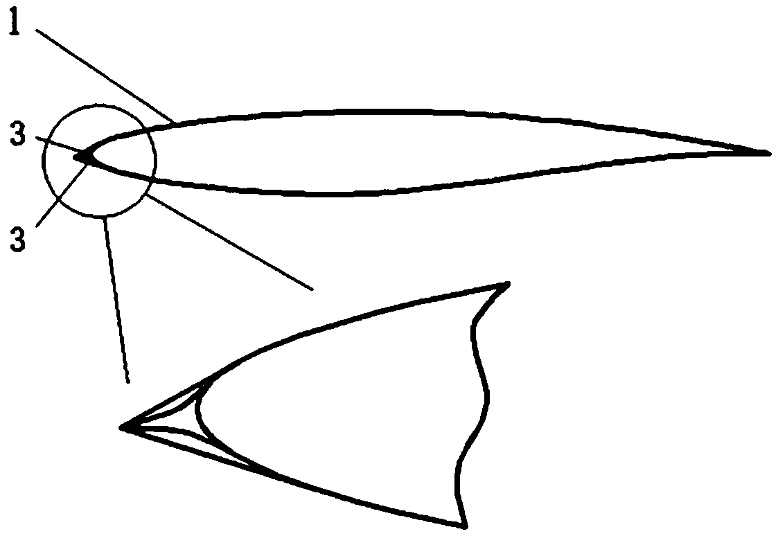
  • Variable wing leading edge combining subsonic aerodynamic performance and supersonic aerodynamic performance
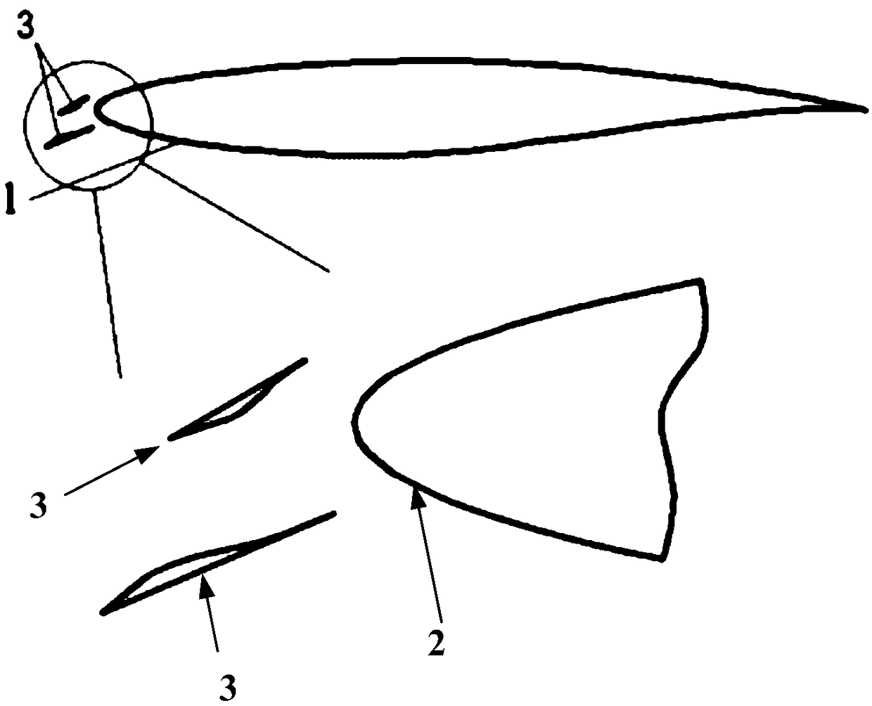
  • Variable wing leading edge combining subsonic aerodynamic performance and supersonic aerodynamic performance
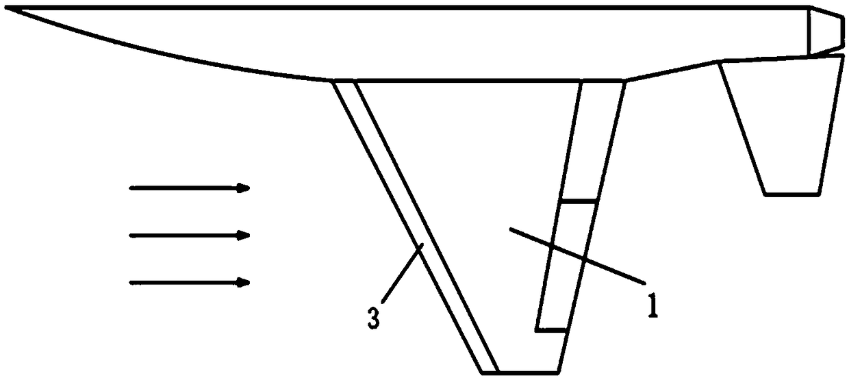
  • Variable wing leading edge combining subsonic aerodynamic performance and supersonic aerodynamic performance

Examples


Embodiment 1

[0027] Example 1: When the flow Mach number is 0.3, the flow Reynolds number is 6.5×10 6 , when the incoming flow angle of attack is 6°, the calculation and verification of the leading edge of the wing of the aircraft is carried out. It can be known from the technical knowledge that the airfoil is the section of the wing in each plane parallel to the aircraft symmetry plane in the span direction, and the flow analysis of the airfoil is equivalent to the analysis of the flow of the wing in a certain section. Figure 5 It is a schematic diagram of the airflow streamline of the traditional sharp wing leading edge in subsonic flight state. The sharp wing leading edge 5 surface produces leading edge separation bubbles 6, and the lift-to-drag ratio is low when the aircraft is flying at subsonic speed. Using the traditional sharp wing The lift coefficient of wing leading edge 5 under the condition that present embodiment provides is 0.77124, and drag coefficient is 0.022767, and lift...

Embodiment 2

[0028] Example 2: When the flow Mach number is 2.2, the flow Reynolds number is 3.2×10 7 , when the incoming flow angle of attack is 2°, the calculation and verification of the leading edge of the wing of the aircraft is carried out. Such as Figure 7 Shown is a schematic diagram of the pressure distribution of the conventional blunt wing leading edge under supersonic flight. The obvious pressure dividing line in front of the wing leading edge is the shock wave. The shock wave presents a bow shape, which brings a large In this state, the lift coefficient of the wing with blunt wing leading edge when the aircraft flies at supersonic speed is 0.13917, the drag coefficient is 0.17941, and the lift-to-drag ratio is 0.78; Figure 8 In order to adopt the variable wing leading edge of the present invention to carry out the pressure distribution diagram of supersonic flight, the movable leading edge baffle 3 of the wing adopting the variable wing leading edge design is retracted so t...


PUM


Abstract

The invention discloses a variable wing leading edge combining subsonic aerodynamic performance and supersonic aerodynamic performance, and belongs to the technical field of aerodynamic design of aircrafts. The variable wing leading edge is formed by mounting two movable leading edge baffles on the upper and lower sides of the wing leading edge through connecting rods respectively, and the two movable leading edge baffles make contact to form a sharp wing leading edge during supersonic flight; during subsonic flight, the two movable leading edge baffles translate forwards and rotate respectively to expose the wing leading edge, and an open slot structure is formed between each movable leading edge baffle and the wing leading edge. By means of the variable wing leading edge, the shape of the wing leading edge can be changed reasonably by the two movable leading edge baffles according to different environments in a flight process of an aircraft, the aircraft can obtain higher lift-drag ratio in supersonic and subsonic flight states, and use cost can be reduced.

Description

technical field [0001] The invention belongs to the technical field of aircraft aerodynamic design, and relates to a variable wing leading edge that takes into account both subsonic and supersonic aerodynamic performances, in particular to a wing leading edge that adopts a variable geometric shape to improve the performance of an aircraft against subsonic and supersonic speeds. Adaptability to sonic flight conditions, taking into account the design of aerodynamic efficiency in different flight conditions. Background technique [0002] In order to reduce the impact of sonic booms generated during flight on people’s lives, aircraft are expressly prohibited from flying at supersonic speeds over human-inhabited areas. Capable aircraft can only fly at subsonic speeds in such areas. The ability of aircraft to fly at supersonic speed is mostly reflected by the sharp wing leading edge of the wing, and the radius of the wing leading edge of this sharp wing leading edge wing can be r...

Claims


Application Information

Patent Timeline
Patent Type & Authority Applications(China)
IPC IPC(8): B64C3/28B64C30/00
CPCB64C3/28B64C30/00
Inventor 蒋崇文李志豪何新欧阳忠杰高振勋
Owner BEIHANG UNIV
Learn More