
Aircraft head-on resistance and heat reduction method

A technology of aircraft and thermal method, applied in aircraft parts, fuselage, transportation and packaging to achieve the effect of reducing shock wave resistance and reducing heat flow

Pending Publication Date: 2022-02-15
INST OF MECHANICS - CHINESE ACAD OF SCI
View PDF0 Cites 0 Cited by
  • Summary
  • Abstract
  • Description
  • Claims
  • Application Information

AI Technical Summary

Problems solved by technology

[0006] To this end, the embodiment of the present invention provides a method for reducing drag and heat in the face of an aircraft to solve the problems of wave resistance and heat flow caused by shock waves when the aircraft is flying against the wind in the prior art

Method used


Image

  • Aircraft head-on resistance and heat reduction method
  • Aircraft head-on resistance and heat reduction method
  • Aircraft head-on resistance and heat reduction method

Examples


Embodiment 1

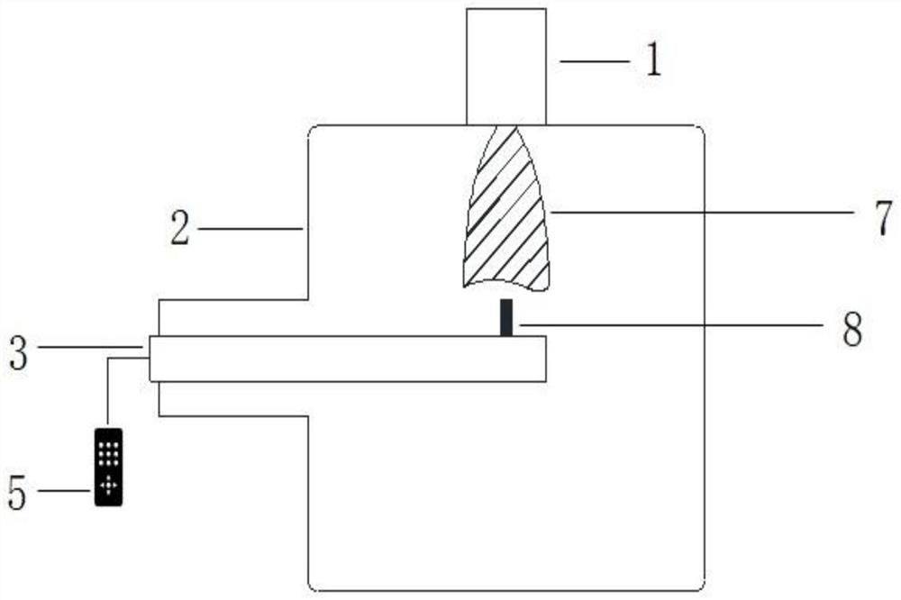
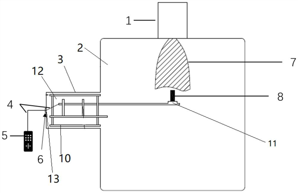
[0026] like figure 2 , image 3 and Figure 4 As shown, a aircraft is slightly reduced by the heating method, and the configuration entity is provided in the head of the aircraft, which can be ablated into a sharp structure in the aircraft flight, to maintain the hustle The transition is a tapered hike to reduce the hustle resistance to the aircraft.

[0027] The present invention mainly passes through the head to a sharp-shaped nasal cone structure, and the configuration entity can be kept in the shape throughout the process, and the arcuate hindle can be converted to the on-one manner. Conical hike, thereby effectively reducing hustle resistance; on the other hand, it can also reduce the surface heat flow of the aircraft body.

Embodiment 2

[0029] like figure 2 , image 3 and Figure 4 As shown, a aircraft is slightly reduced by the aircraft, and a configuration entity is provided in the aircraft head, and the configuration entity extends along the front end of the aircraft, and the structural entity uses a material having thermal lifting characteristics. A tip structure or cylindrical structure is prepared, the tip structure maintains the configuration in the ablation process, which is burn into a sharp configuration in the ablation process and maintained.

[0030] Further, such as figure 2 , image 3 and Figure 4 As shown, a aircraft is averaged, and the graphite cylinder is provided in the front end of the aircraft. The graphite cylinder has thermal lifting characteristics and can protect the characteristics of ablation, the length direction of the graphite cylinder along the aircraft The head is extended outwardly, and one end portion of the graphite cylinder is positively received on the head of the aircraft, and t...


PUM


Abstract

The invention belongs to the technical field of pneumatic heat protection, and aims at providing an aircraft head-on resistance and heat reduction method to solve the technical problem that in the prior art, the requirement for heat protection of the aircraft is higher and higher. The configuration entity made of the material which has the heat sublimation characteristic and can be ablated in a shape-preserving mode is arranged at the front end of the aircraft in a protruding mode, on one hand, arch shock waves can be converted into conical shock waves through shape-preserving ablation of the configuration entity, so that the range of approximate normal shock waves in front of the aircraft is reduced, the wave resistance of oblique shock waves is smaller than that of the normal shock waves, and the shock wave resistance can be effectively reduced; on the other hand, heat flow borne by the surface of the aircraft body can be reduced, and heat protection is conducted on the aircraft.

Description

Technical field [0001] The present invention belongs to the field of thermal protection, and in particular, the present invention relates to a method of preventing heat loss and heat treatment of aircraft. Background technique [0002] Wind tunnel test is an important means of studying the mechanical properties of materials in the near real flight environment. A small plasma wind hole can be used to stabilize a high energy flow density for a long time, suitable for high enthalpy flow at the wall surface of the simulated material. Small plasma wind holes For local feature hot environments on small samples, the small sample is carried out, and the study of material ablation characteristics has a unique advantage: it has relatively simple operation, low operating cost, good controllability, Initial use of high-temperature ablation characteristics of bulk materials, it provides a basis for the large-scale screening of materials. It is suitable for research on high-temperature perform...

Claims


Application Information

Patent Timeline
Patent Type & Authority Applications(China)
IPC IPC(8): B64C1/00B64C1/38
CPCB64C1/0009B64C1/38
Inventor 韩宁曹进文黄河激
Owner INST OF MECHANICS - CHINESE ACAD OF SCI
Learn More