

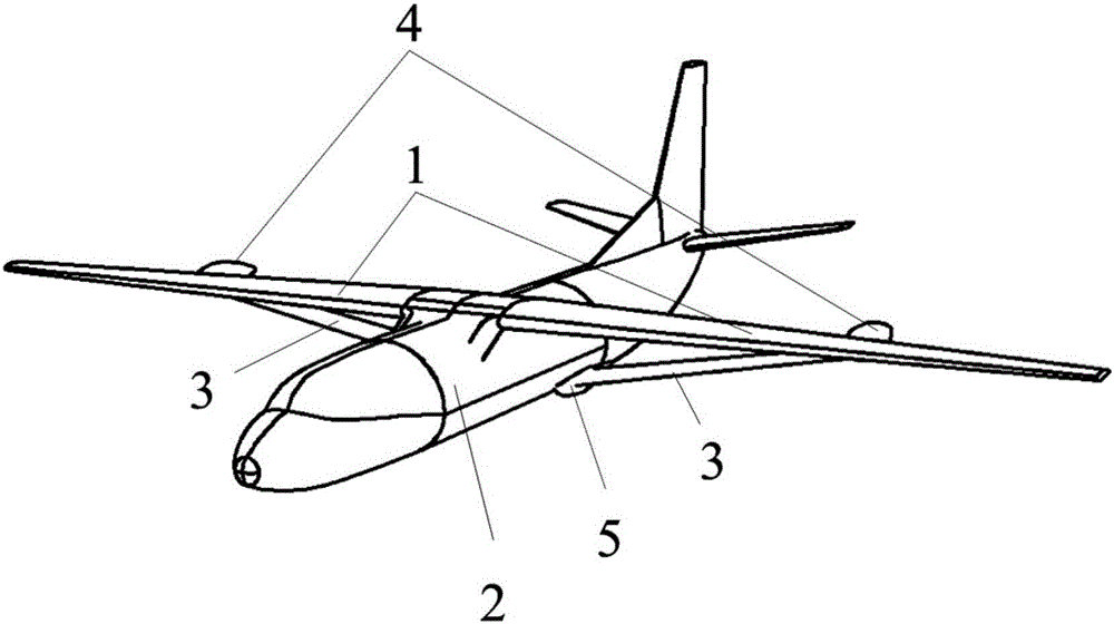
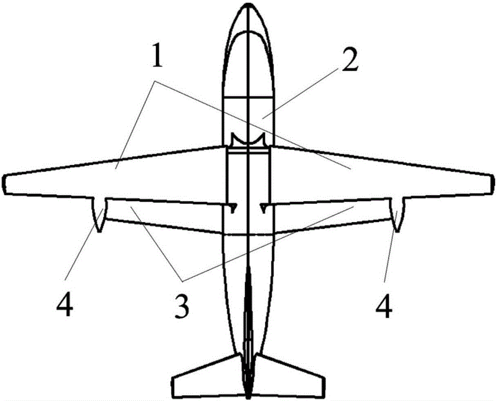
Air vehicle aerodynamic configuration with trailing edge supporting wing
An aerodynamic layout and support wing technology, which is applied to aircraft parts, aircraft control, aircraft stability, etc., can solve the problems of reduced aerodynamic efficiency, low aerodynamic efficiency, and reduced lift-to-drag ratio of aircraft, achieving lift-to-drag ratio improvement and aerodynamic considerations Efficiency and structural efficiency, the effect of reducing structural weight
- Summary
- Abstract
- Description
- Claims
- Application Information
AI Technical Summary
Problems solved by technology
Method used
Image


Examples
Embodiment 1
[0028] Embodiment 1: Both the main wing 1 and the supporting wing 3 adopt Clark-Y airfoil; the chord length of the main wing 1 is 2m, and the reference length of the chord length of the supporting wing 3 is 1m; the supporting wing 3 is designed to span upward in the model of the supporting wing 3 In each section of the main wing 1 and the section of the supporting wing 3 taken along the vertical plane during the flight of the aircraft, the vertical distance between the centroids is 10% of the chord length of the main wing 1 section, and the chord line of the section of the main wing 1 and the supporting wing The 3-section chord overlaps the length of the 1-section chord of the main wing by 11%. Figure 6a , 6b The two-dimensional analysis curves of the lift coefficient and lift-drag ratio of the above-mentioned supported wing 3 layout compared with the unsupported single-wing layout are given respectively. The lift of the supported wing layout is the sum of the lift of the two...
Embodiment 2
[0029] Embodiment 2: the main wing and the supporting wing all adopt the Clark-Y airfoil; the chord length of the main wing is 2m, and the chord length of the supporting wing is 1m; in the model of the supporting wing 3, the design supporting wing 3 spreads upwards and each along the airflow during the flight of the aircraft In the section of the main wing 1 and the section of the supporting wing 3 intercepted by the flow direction vertical plane, the vertical distance between the centroids is 40% of the chord length of the section of the main wing 1, and the overlapping length of the chord line of the main wing 1 section and the section chord of the supporting wing 3 is 0% of the chord line of the main wing 1 section, that is, there is no overlap between the two; the installation angle of the main wing 1 section is φ 1 =0°, the installation angle of the supporting wing 3 section is φ 2 , then the installation angle difference between the main wing 1 and the support wing 3 sec...
PUM
 Abstract
Description
Claims
Application Information